Photoelectric encoder coded disc, photoelectric detection device, photoelectric encoder and robot

A photoelectric encoder and photoelectric detection technology, applied in the encoder field, can solve the problems of unstable connection between the control circuit board and the light source emitting unit and the light source receiving unit, affecting the photoelectric signal transmission, etc., and achieves good photoelectric signal transmission and anti-noise performance. Good and stable overall structure

Inactive Publication Date: 2017-01-25
SHANGHAI XPARTNER ROBOTICS
View PDF9 Cites 5 Cited by
  • Summary
  • Abstract
  • Description
  • Claims
  • Application Information

AI Technical Summary

Problems solved by technology

In the existing design, the code disc of the photoelectric encoder is a disc structure, which must be placed in the groove of the photoelectric detection device, and the light source emitting unit and the light source receiving unit must also be connected with the control circuit board including the photoelectric conversion circuit and the photoelectric processing circuit. At this time, the light source emitting unit and the light source receiving unit need to be set above the control circuit board and ensure that they are electrically connected to the control circuit board. This design will not only cause unstable connection between the control circuit board and the light source emitting unit and light source receiving unit. It will also affect the transmission of photoelectric signals

Method used


Image

  • Photoelectric encoder coded disc, photoelectric detection device, photoelectric encoder and robot
  • Photoelectric encoder coded disc, photoelectric detection device, photoelectric encoder and robot
  • Photoelectric encoder coded disc, photoelectric detection device, photoelectric encoder and robot

Examples


Embodiment Construction

[0025] The technical solutions of the present invention will be further described below in conjunction with the accompanying drawings and through specific implementation methods.

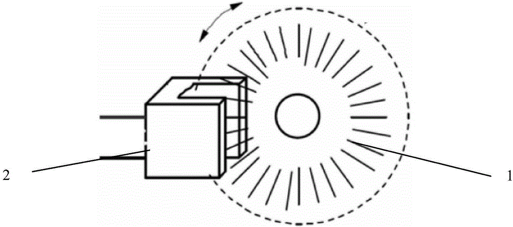
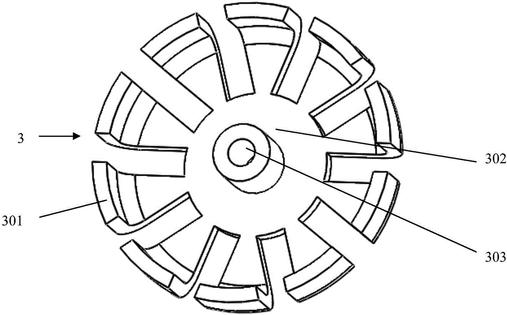
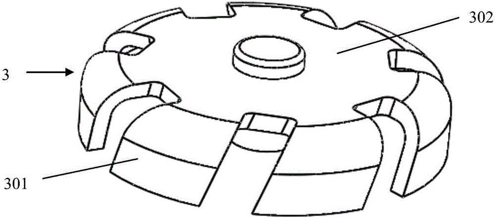
[0026] Such as figure 2 As shown, the code disc 3 of the photoelectric encoder is composed of a code reading plate 301 and a disc body 302. The disc body 302 is in the shape of a gear, and a code reading plate 301 is vertically connected to each gear tooth. The code reading plates 301 are all located on the disc body 302. On the same side, and the width extension direction of each code reading plate 301 is the same as the width extension direction of the teeth connected to the code reading plate 301, the photoelectric encoder code disc 3 is in the shape of a squirrel cage as a whole. This squirrel-cage design can effectively reduce the area of ​​the disc body 302, and it is not necessary to place the light source emitting unit 401 and the light source receiving unit 402 on both sides of the disc bo...


PUM


Abstract

The invention discloses a photoelectric encoder coded disc, a photoelectric detection device, a photoelectric encoder and a robot, and belongs to the technical field of encoders. The photoelectric encoder coded disc comprises a gear-shaped disc body and a code reading plate which is perpendicularly connected with the gear-shaped disc body, and the whole photoelectric encoder coded disc is in the shape of a mouse cage. The photoelectric detection device comprises a light source transmitting unit, a light source receiving unit and a control circuit board, and when the photoelectric encoder coded disc is used with the photoelectric detection device, the code reading plate is inlaid between the light source transmitting unit and the light source receiving unit. By the mouse-cage-shaped structure of the photoelectric encoder coded disc, the light source transmitting unit and the light source receiving unit are not required to be placed on two sides of an end surface of the disc-shaped coded disc, so that a control circuit board can be stably connected with the light source transmitting unit and the light source receiving unit, photoelectric signals are transmitted well, the whole structure of the photoelectric encoder is stable, anti-noise performance in signal transmission is good, and the shock resistance is high.

Description

technical field [0001] The invention relates to the technical field of encoders, in particular to a photoelectric encoder code disc, a photoelectric detection device, a photoelectric encoder and a robot. Background technique [0002] A photoelectric encoder is a sensor that converts the mechanical geometric displacement on the output shaft into a pulse or digital quantity through the principle of photoelectric conversion, and is now mostly used to measure the speed of the motor. Such as figure 1 As shown, the photoelectric encoder in the prior art is composed of a photoelectric encoder code disc 1 (grating disc) and a photoelectric detection device 2, and the structure of the photoelectric encoder code disc 1 is mostly opened in equal parts on a circular plate with a specific diameter. A rectangular hole, the photoelectric detection device 2 includes a light source emitting unit, a light source receiving unit and a control circuit board, the photoelectric detection device 2...

Claims


Application Information

Patent Timeline
Patent Type & Authority Applications(China)
IPC IPC(8): G01D5/347
CPCG01D5/3473
Inventor 恽为民李来法吴兵勇武辉明庞作伟
Owner SHANGHAI XPARTNER ROBOTICS
Why Eureka
Try Eureka