On-line blast furnace charge level measuring system and method

A technology of blast furnace material level and measurement system, applied in the field of online measurement system of blast furnace material level, can solve the problems of inability to measure the discharge surface information in real time and completely, and achieve complete acquisition of material level information, high measurement accuracy, and short measurement time short effect

Pending Publication Date: 2017-01-25
MCC CAPITAL ENGINEERING & RESEARCH
View PDF5 Cites 3 Cited by
  • Summary
  • Abstract
  • Description
  • Claims
  • Application Information

AI Technical Summary

Problems solved by technology

[0004] The purpose of the present invention is to overcome the defect in the prior art that the discharge surface information cannot be measured in real time and completely in the blast furnace, thereby providing an online measurement system and method for the blast furnace discharge surface, the system comprising: a first laser scanner And the image processing equipment connected to the laser scanner; the first laser scanner is installed on the lower surface platform at the chute inspection hole on the blast furnace roof cover through a fixed rod, to scan complete material level information and send it to The image processing device, the image processing device generates a three-dimensional material level image of the blast furnace material level according to the material level information; the lower surface platform at the inspection hole of the chute is also provided with a fixed rod slideway, and the fixed rod Installed in the slideway of the fixed rod; the first laser scanner slides up and down along the fixed rod, and the fixed rod slides along the slideway of the fixed rod to adjust the horizontal position of the first laser scanner; The first laser scanner is a 3D laser scanner

Method used


Image

  • On-line blast furnace charge level measuring system and method
  • On-line blast furnace charge level measuring system and method
  • On-line blast furnace charge level measuring system and method

Examples


Embodiment Construction

[0040] The following will clearly and completely describe the technical solutions in the embodiments of the present invention with reference to the accompanying drawings in the embodiments of the present invention. Obviously, the described embodiments are only some, not all, embodiments of the present invention. Based on the embodiments of the present invention, all other embodiments obtained by persons of ordinary skill in the art without making creative efforts belong to the protection scope of the present invention.

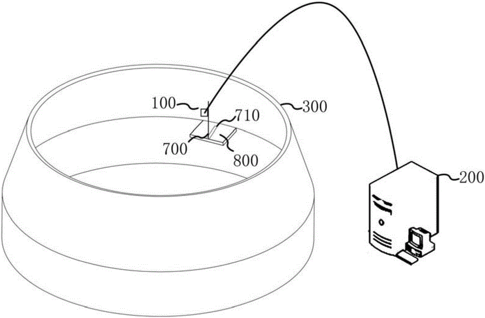
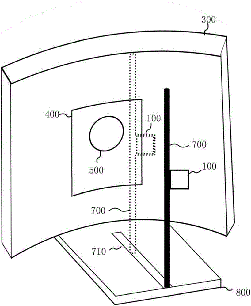
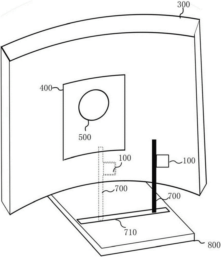
[0041] figure 1 It is a schematic diagram of an on-line measurement system of the blast furnace charge level according to an embodiment of the present invention, such as figure 1 As shown, the online measurement system of the blast furnace charge level of the present invention includes: a first laser scanner 100 and an image processing device 200 connected to the laser scanner; the first laser scanner 100 is installed on the top of the blast furnace to scan th...


PUM


Abstract

The invention provides an on-line blast furnace charge level measuring system and method. The on-line blast furnace charge level measuring system comprises a first laser scanner and image processing equipment connected with the laser scanner; the first laser scanner is installed at the top of a blast furnace to scan complete charge level information and transmit the charge level information to the image processing equipment, the image processing equipment generates a three-dimensional charge level image of the blast furnace charge level according to the charge level information, and the first laser scanner is a three-dimensional laser scanner. The charge level is comprehensively scanned through the three-dimensional laser scanner installed in the blast furnace and a slide way of a fixing rod, the scanning process is high in automation degree, short in measuring time, high in measuring accuracy, and on-line real-time and complete three-dimensional charge level images can be obtained to obtain charge level information meeting the practicality better then. The requirements for observing the charge level shape more visually and obtaining the chare level information more completely are met truly.

Description

technical field [0001] The invention relates to the field of blast furnace measurement in iron and steel metallurgy, in particular to an online measurement system and method for blast furnace material level. Background technique [0002] With the continuous improvement of blast furnace ironmaking technology and equipment, breakthroughs have been made in blast furnace online monitoring and diagnosis technology. Especially in the online monitoring of the furnace top, from the initial furnace top camera, to infrared imaging, and now to the current laser scanning online measurement of material level technology, the perspective of the top of the blast furnace is becoming clearer and more effective in guiding the operation of the blast furnace. bigger and bigger. In particular, laser on-line measurement of material level technology has made great progress in both software and hardware of the system, and is gradually at the forefront of on-line monitoring and diagnosis of blast fu...

Claims


Application Information

Patent Timeline
Patent Type & Authority Applications(China)
IPC IPC(8): G01F23/00
CPCG01F23/00
Inventor 杜鹏宇全强李永军傅源荻凌树渊
Owner MCC CAPITAL ENGINEERING & RESEARCH
Why Eureka
Try Eureka