
Wear tester for electric power fittings

A wear test and power fitting technology, which is applied in the direction of testing wear resistance, etc., can solve the problems that the load cannot be adjusted according to the needs, the wear test results are not accurate enough, and the damage performance of the power fitting is large, so as to save the electric system and the control box. , The structure is simple and labor-saving, and the labor-saving effect is obvious.

Active Publication Date: 2017-01-25
ELECTRIC POWER SCI RES INST OF STATE GRID XINJIANG ELECTRIC POWER +2
View PDF11 Cites 6 Cited by
  • Summary
  • Abstract
  • Description
  • Claims
  • Application Information

AI Technical Summary

Problems solved by technology

[0002] In the actual project of wind resistance of transmission towers, in order to study the wear of the connecting hardware in the transmission tower line, a variety of wear testing machines have been developed and adopted, but the loaders of most wear testing machines can only apply static loads, which are more suitable. Dynamic loads in the form of actual loads, such as wind loads
The wind load can be simplified as a simple harmonic dynamic load. The simple harmonic dynamic load produces a continuously changing tensile stress on the electric fittings. The changing tensile stress is more destructive to the electric fittings, aggravates the wear of the electric fittings, and further shortens the life of the fittings. , so the wear test results of the wear testing machine in the prior art are not accurate enough, and can only play a rough detection effect. In addition, the existing wear testing machine uses large weights one by one, and the weight of the large weight If the weight is large, either add the weight of the entire weight, or remove the weight of the entire weight, so that the load added by the loader cannot be adjusted as needed

Method used


Image

  • Wear tester for electric power fittings
  • Wear tester for electric power fittings
  • Wear tester for electric power fittings

Examples


Embodiment Construction

[0033] The present invention will be described in further detail below in conjunction with the accompanying drawings and specific embodiments.

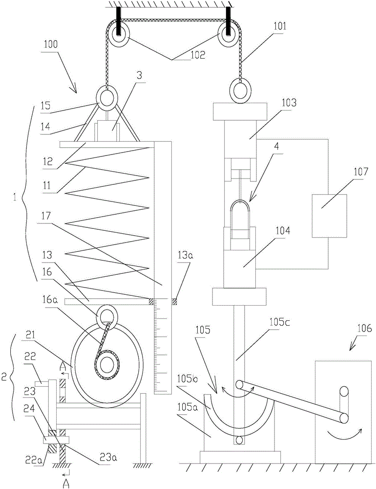
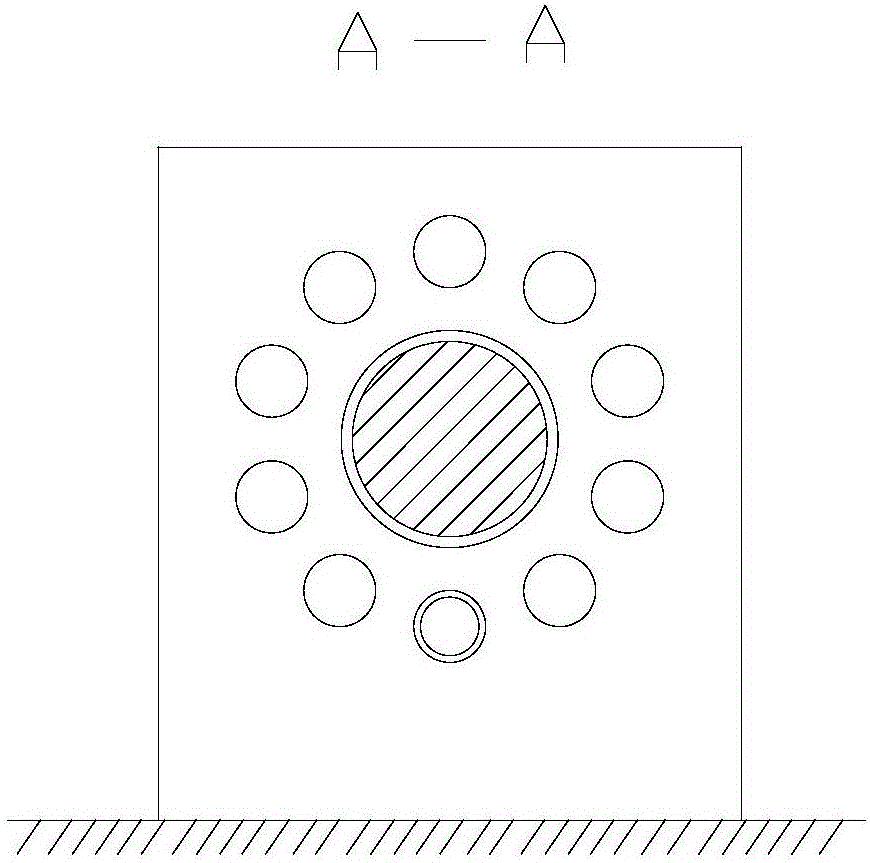
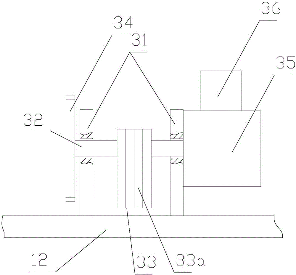
[0034] Such as figure 1 , figure 2 , image 3 , Figure 4As shown, the present invention provides a wear tester for electric power fittings, including a frame, and a load machine 100 arranged on the frame, the upper end of the load machine 100 is connected with a first suspension rope 101, and the first suspension The rope 101 is connected with the upper suspension device 103 after bypassing the pulley combination 102 hoisted on the top of the frame, and the lower suspension device 104 is arranged opposite to the upper suspension device 103. 105 includes a guide rail fixing plate 105a fixed on the bottom of the frame, an arc-shaped guide rail 105b installed on the guide rail fixing plate 105a, and a swing rod rolling sleeve 105c that can slide along the guide rail 105b. The upper part of the swing rod rolling sleeve 105c is connec...


PUM


Abstract

The invention discloses a wear tester for electric power fittings, comprising a frame and a load carrier arranged on the frame; the upper end of the load carrier is connected with a first hanging rope which runs through a pulley set hung at the top of the frame and is then connected with an upper hanging device, a lower hanging device corresponds to the upper hanging device, the lower hanging device is connected with a rocking device, the rocking device is also connected with a power unit, the load carrier comprises a spring mechanism, a winding mechanism and a vibration exciter, the upper end of the spring mechanism is connected with the other end of the first hanging rope, the lower end of the spring mechanism is connected with the winding mechanism, the vibration exciter is also arranged on the spring mechanism, and the vibration exciter applies dynamic load to the spring mechanism. The loader carrier that considers both dead load and simple harmonic load is used provided to simulate load of an electric power fitting in actual engineering application, such that wear results of the tester are more precise and more practical.

Description

technical field [0001] The invention relates to a detection device for electric fittings, in particular to a wear testing machine for electric fittings. Background technique [0002] In the actual project of wind resistance of transmission towers, in order to study the wear of the connecting hardware in the transmission tower line, a variety of wear testing machines have been developed and adopted, but the loaders of most wear testing machines can only apply static loads, which are more suitable. Dynamic loads in the form of actual loads, such as wind loads. The wind load can be simplified as a simple harmonic dynamic load. The simple harmonic dynamic load produces a continuously changing tensile stress on the electric fittings. The changing tensile stress is more destructive to the electric fittings, aggravates the wear of the electric fittings, and further shortens the life of the fittings. , so the wear test results of the wear testing machine in the prior art are not ac...

Claims


Application Information

Patent Timeline
IPC IPC(8): G01N3/56
CPCG01N3/56
Inventor 赵建平何成李文胜张龙王灵芝晏致涛王欣欣刘阳崔晓东徐凯
Owner ELECTRIC POWER SCI RES INST OF STATE GRID XINJIANG ELECTRIC POWER
Learn More