Excess loop delay compensation circuit, excess loop compensation method and continuous time delta-sigma analog-digital converter

An analog-to-digital converter and loop delay technology, applied in the field of analog-to-digital converter design, can solve problems such as difficult to accurately quantify, the effect of ELD compensation, etc., and achieve the effect of flexible ELD compensation

Inactive Publication Date: 2017-01-25
SANECHIPS TECH CO LTD
View PDF6 Cites 2 Cited by
  • Summary
  • Abstract
  • Description
  • Claims
  • Application Information

AI Technical Summary

Problems solved by technology

[0006] However, the above-mentioned ELD compensation scheme has the following problems: the ELD time τ eld In the actual circuit, it will be affected by many factors, and it is difficult to quantify it accurately, which will affect the effect of ELD compensation

Method used


Image

  • Excess loop delay compensation circuit, excess loop compensation method and continuous time delta-sigma analog-digital converter
  • Excess loop delay compensation circuit, excess loop compensation method and continuous time delta-sigma analog-digital converter
  • Excess loop delay compensation circuit, excess loop compensation method and continuous time delta-sigma analog-digital converter

Examples


no. 1 example

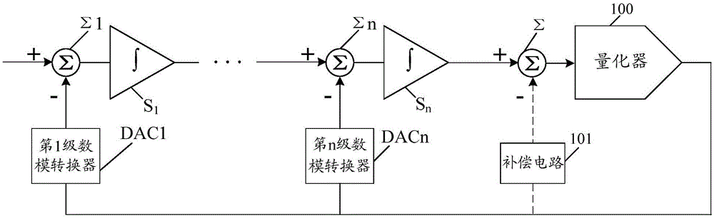
[0038] An embodiment of the present invention provides an ELD compensation circuit, which is used for ELD compensation for the ELD time of a continuous-time delta-sigma analog-to-digital converter. Such as figure 1 As shown, the continuous-time delta-sigma analog-to-digital converter includes a quantizer 100, a first-stage digital-to-analog converter DAC1 to an n-th stage digital-to-analog converter DACn, a first-stage adder Σ1 to an n-th stage adder Σn, and The first stage integrator S1 to the nth stage integrator Sn connected in series sequentially, n is a natural number.

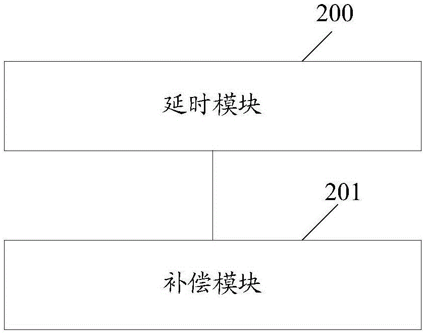
[0039] figure 2 It is a structural schematic diagram of the first embodiment of the ELD compensation circuit of the present invention, as figure 2 As shown, the circuit includes: a delay module 200 and a compensation module 201 .

[0040] The first embodiment of the ELD compensation circuit of the present invention will be described below in two cases.

[0041] The first case: the delay module 200 i...

no. 2 example

[0076] The embodiment of the present invention also proposes a continuous-time delta-sigma analog-to-digital converter, and the continuous-time delta-sigma analog-to-digital converter includes any ELD compensation circuit in the first embodiment of the present invention.

no. 3 example

[0078] Based on the ELD compensation circuit of the embodiment of the present invention, the embodiment of the present invention also proposes an ELD compensation method, the method comprising:

[0079] A delay module is provided for the continuous time delta-sigma analog-to-digital converter, and the delay module selects a delay time among multiple preset delay times, and delays the signal received by itself for output based on the selected delay time.

[0080] ELD compensation is performed on the ELD time of the continuous-time delta-sigma analog-to-digital converter according to the delayed output signal of the delay module.

[0081] Here, the continuous-time delta-sigma analog-to-digital converter includes a quantizer, a first-stage digital-to-analog converter to an n-th stage digital-to-analog converter, and a first-stage integrator to an n-th stage integrator sequentially connected in series , n is a natural number; wherein, the i-th stage digital-to-analog conver...


PUM


Abstract

An embodiment of the invention discloses an ELD (excess loop delay) compensation circuit. The ELD compensation circuit is used for carrying out ELD compensation on ELD time of a continuous time delta-sigma analog-digital converter and comprises a delay module and a compensation module. The delay module is used for selecting a time delay among a plurality of preset time delays and outputting received signals in a delayed manner on the basis of the selected time delay; the compensation module is used for carrying out ELD compensation according to the signals outputted by the delay module in the delay manner. The embodiment of the invention further discloses an ELD compensation method and the continuous time delta-sigma analog-digital converter.

Description

technical field [0001] The invention relates to the field of analog-to-digital converter design, in particular to an extra loop delay (excess loopdelay, ELD) compensation circuit, method and continuous time delta-sigma analog-to-digital converter. Background technique [0002] In the field of wireless communication, continuous-time delta-sigma analog-to-digital converters are attracting more and more attention. Compared with discrete-time delta-sigma ADCs, continuous-time delta-sigma ADCs reduce the bandwidth requirements of operational amplifiers, which in turn can reduce the power consumption of the circuit. In addition, due to the inherent anti-aliasing characteristics and insensitivity to process deviations of the continuous-time delta-sigma analog-to-digital converter, it is very beneficial to be applied in radio frequency (Radio Frequency, RF) receivers. [0003] figure 1 It is a schematic diagram of the composition structure of the continuous time delta-sigma analog...

Claims


Application Information

Patent Timeline
Patent Type & Authority Applications(China)
IPC IPC(8): H03M3/00
CPCH03M1/06H03M3/00
Inventor 郑宇亮
Owner SANECHIPS TECH CO LTD
Why Eureka
Try Eureka