Detecting device for input optical power of set-top box
A technology of power detection and input light, which is applied in transmission systems, electromagnetic wave transmission systems, electromagnetic receivers, etc., and can solve the problem that optical fiber input set-top boxes cannot directly detect input signals
- Summary
- Abstract
- Description
- Claims
- Application Information
AI Technical Summary
Problems solved by technology
Method used
Image

Examples
Embodiment 1
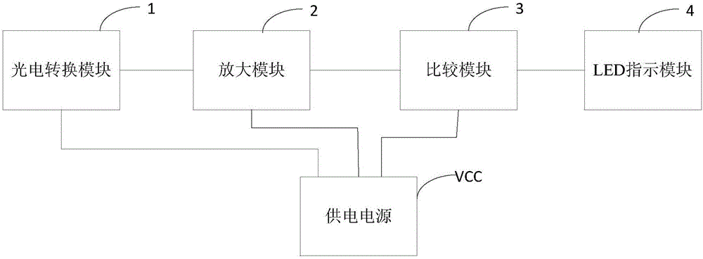
[0025] figure 1 It is a functional block diagram of a device for detecting input optical power of a set-top box provided in Embodiment 1 of the present invention. Such as figure 1 As shown, the device includes a photoelectric conversion module 1, an amplification module 2, a comparison module 3, an LED indicator module 4 and a power supply VCC.
[0026] The power supply VCC is used to supply power to the photoelectric conversion module 1 , the amplification module 2 , the comparison module 3 and the LED indication module 4 . The amplification module 2 includes an amplification unit and a magnification adjustment unit. The comparison module 3 includes a comparison unit and a comparison range adjustment unit. The LED indicating module 4 includes an LED driving circuit and an LED adjusting circuit. The output end of the photoelectric conversion module 1 is connected to the input end of the amplification module 2 , and the photoelectric conversion module 1 converts the receive...
Embodiment 2
[0028] On the basis of the first embodiment, the second embodiment is obtained by specifically selecting the implementation circuits of the amplification module 2 , the comparison module 3 , and the LED indication module 4 . Embodiment 2 provides a set-top box input optical power detection device, the device includes a photoelectric conversion module 1, an amplification module 2, a comparison module 3, an LED indicator module 4 and a power supply VCC, and the power supply VCC is the photoelectric conversion module 1 and the amplification module 2 , The comparison module 3 supplies power.
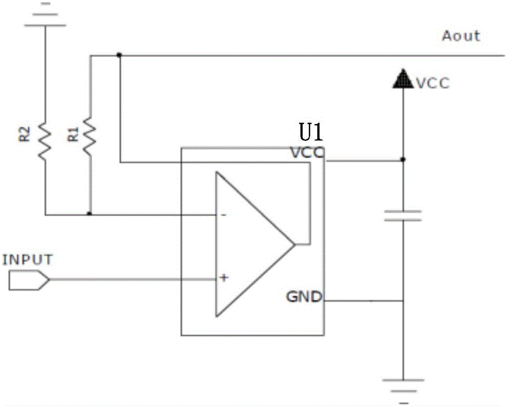
[0029] figure 2 A schematic circuit diagram of the amplification module 2 of the set-top box input optical power detection device provided by Embodiment 2 of the present invention. Such as figure 2 As shown, the amplifying module 2 includes an amplifier U1, a resistor R1, and a resistor R2. One end of the resistor R2 is grounded, the other end of the resistor R2 and one end of the resist...
PUM
 Abstract
Description
Claims
Application Information
 - R&D
- Intellectual Property
- Life Sciences
- Materials
- Tech Scout
- Unparalleled Data Quality
- Higher Quality Content
- 60% Fewer Hallucinations
Browse by: Latest US Patents, China's latest patents, Technical Efficacy Thesaurus, Application Domain, Technology Topic, Popular Technical Reports.
© 2025 PatSnap. All rights reserved.Legal|Privacy policy|Modern Slavery Act Transparency Statement|Sitemap|About US| Contact US: help@patsnap.com