Small-sized combine harvester with grain tank and adjustable grain discharging device
A technology for combine harvesters and grain unloading devices, which is applied to harvesters, agricultural machinery and implements, cutters, etc. It can solve problems that affect operating efficiency, irregular fields, and wet and rotten fields, so as to reduce transportation time and The effect of labor, unloading grain is convenient and free, and preventing the cantilever from being too long
- Summary
- Abstract
- Description
- Claims
- Application Information
AI Technical Summary
Problems solved by technology
Method used
Image
Examples
Embodiment 1
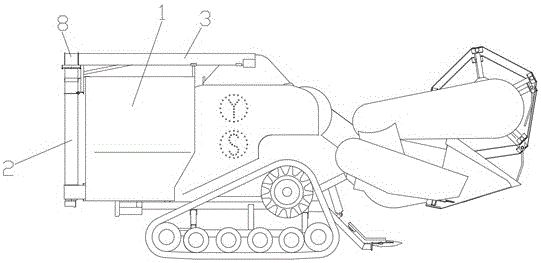
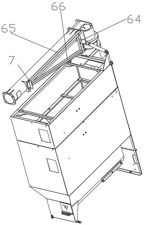
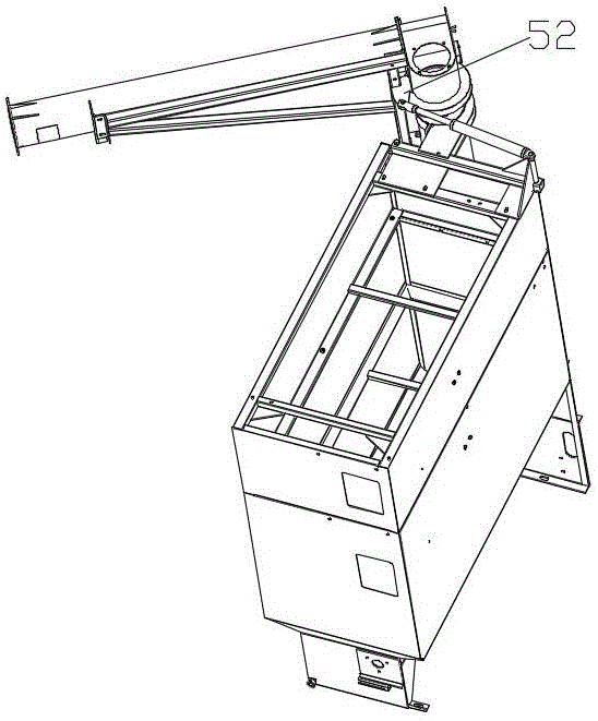
[0037] A small combine harvester with a grain tank and an adjustable grain unloading device includes a frame, and also includes a grain box assembly arranged at the rear of the frame, the grain box assembly including a grain box fixed on the frame. Box 1. A vertical auger pipe with a vertical auger fixed inside the grain tank and the bottom connected to the bottom of the grain tank. 2. A horizontal auger inside and one end of the vertical auger pipe is connected to the other end. It is the horizontal auger pipe 3 of the grain unloading port. The horizontal auger pipe is rotatably connected with the vertical auger pipe through the connecting pipe. The rotating assembly that the vertical auger tube rotates.
[0038] In the present application, the entire structure is more compact and space-saving when no grain is placed through the horizontal augers that can be rotated around the top of the vertical augers to ensure the flexibility of the small harvester, and the horizontal auge...
Embodiment 2
[0054] The difference from the above-mentioned embodiment is that the arc-shaped plate is provided with an arc-shaped hole concentric with the arc-shaped plate and penetrates up and down, and the bottom surface of the mounting plate is provided with an anti-collapse limit strip. The anti-collapse limit bar is narrower than the width of the arc hole. When the boom rotates, the anti-collapse limit bar slides in the arc-shaped hole. One is to prevent the support frame from being damaged and collapsed, and to install the plate frame to the arc-shaped plate to ensure safety. The other is to limit the range of rotation of the horizontal auger tube. Make sure to turn securely without over-twisting.
Embodiment 3
[0056] The difference from the above embodiment is that the grain tank is arranged on one side of the rear of the frame, specifically installed on the right side of the rear of the frame, and is located on two sides of the frame different from the intermediate conveying device, the whole structure is more compact, Reasonable. The vertical auger pipe is fixed on the rear of the grain tank and away from the outer side of the inner side of the grain tank near the center of the frame, and the rear end of the rotating oil cylinder is erected on the top of the grain tank near the inner side. On the inner side, the horizontal auger rod is parallel to the horizontal auger tube and is located on the side of the horizontal auger tube facing the inner side of the grain tank. The horizontal auger tube is fixed with a positioning flap, and the positioning flap includes a fixed plate with an arc adapted to the outer wall of the horizontal auger tube and welded on the horizontal auger tube t...
PUM
 Abstract
Description
Claims
Application Information
 - R&D
- Intellectual Property
- Life Sciences
- Materials
- Tech Scout
- Unparalleled Data Quality
- Higher Quality Content
- 60% Fewer Hallucinations
Browse by: Latest US Patents, China's latest patents, Technical Efficacy Thesaurus, Application Domain, Technology Topic, Popular Technical Reports.
© 2025 PatSnap. All rights reserved.Legal|Privacy policy|Modern Slavery Act Transparency Statement|Sitemap|About US| Contact US: help@patsnap.com


