Engine cylinder oblique-hole processing clamp and aligning method thereof

A technology for engine cylinder blocks and fixtures, which is applied in the direction of manufacturing tools, metal processing equipment, metal processing machinery parts, etc., can solve the problems of huge fixtures, angle errors that cannot be adjusted, and unusable, etc., to achieve accurate alignment, ensure accuracy, Easy to adjust the effect

Active Publication Date: 2017-02-01
海昱科技(台州)有限公司
View PDF10 Cites 1 Cited by
  • Summary
  • Abstract
  • Description
  • Claims
  • Application Information

AI Technical Summary

Problems solved by technology

[0003] In order to process the inclined hole on the engine block in the ordinary vertical centering or drilling and tapping center, it is necessary to use a special fixture. For the fixture that must be inclined in both directions, traditionally, a mechanism for adjusting the angle such as a dial is used. , the use of this mechanism will make the fixture bulky, and it cannot be used on the vertical centering or drilling center with relatively small space; some also directly process the fixture plate as a whole according to the required angle to form Bevel angles in two directions, this method needs to remove a large amount of material, the processing is difficult, and at the same time, the overall weight of the fixture is too large, which affects the high-speed movement performance of the machine tool
In addition, if it is made into an integral type, it will not be able to adjust when an angle error occurs

Method used


Image

  • Engine cylinder oblique-hole processing clamp and aligning method thereof
  • Engine cylinder oblique-hole processing clamp and aligning method thereof
  • Engine cylinder oblique-hole processing clamp and aligning method thereof

Examples


Embodiment Construction

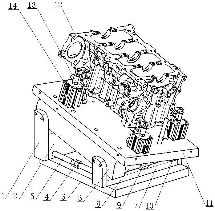
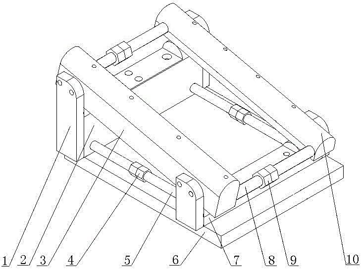
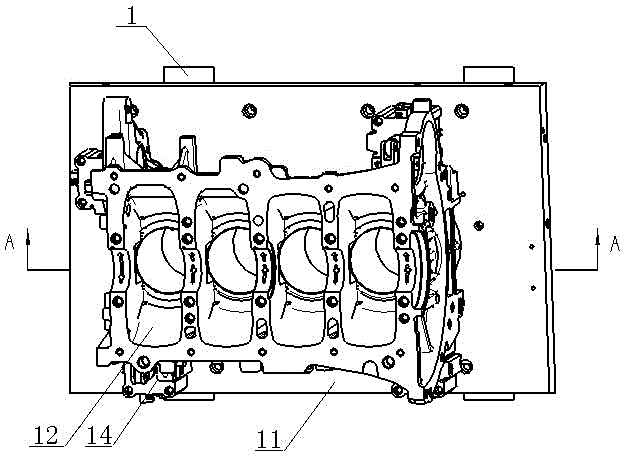
[0027] Below in conjunction with accompanying drawing and specific embodiment, the present invention will be further described: figure 1 , figure 2 , image 3 , Figure 4 As shown, a jig for drilling inclined holes in an engine block includes a jig plate 11 on which a positioning device 13 and a clamping device 14 are arranged. The inclined hole axis 15 on the top is parallel to the main shaft of the machine tool; the left side of the fixture plate 11 is parallel to the YZ plane of the machine tool coordinate system, and the rear side of the fixture plate 11 is parallel to the XZ plane of the machine tool coordinate system; on the fixture plate 11 The bottom is connected with the first vertical support block 3 and the second vertical support block 10, the heights of the first vertical support block 3 and the second vertical support block 10 are not equal, and the first vertical support block 3 and the second vertical support block 10 are unequal in height. The top surface ...


PUM


Abstract

The invention discloses an engine cylinder oblique-hole processing clamp. The engine cylinder oblique-hole processing clamp is characterized in that a clamp plate is arranged in an inclined manner, wherein the left side surface of the clamp plate is parallel to a YZ plane of a machine tool coordinate system, and the rear side surface of the clamp plate is parallel to an XZ plane of the machine tool coordinate system; a first vertical supporting block and a second vertical supporting block are connected below the clamp plate; the top surface of the first vertical supporting block and the top surface of the second vertical supporting block are circular-arc surfaces; the bottom surface of the first vertical supporting block and the bottom surface of the second vertical supporting block are on the same plane which is parallel to the X axis and the Y axis; spacing between the first vertical supporting block and the second vertical supporting block is regulated through a transverse regulating rod; the first vertical supporting block and the second vertical supporting block are arranged on a first transverse supporting block and a second transverse supporting block; the top surface of the first transverse supporting block and the top surface of the second transverse supporting block are circular-arc surfaces, and the bottom surface of the first transverse supporting block and the bottom surface of the second transverse supporting block are on the same horizontal plane; and spacing between the first transverse supporting block and the second transverse supporting block is regulated through a vertical regulating rod. The invention also discloses an aligning method for the engine cylinder oblique-hole processing clamp.

Description

technical field [0001] The invention relates to a machining fixture, in particular to a machining fixture for oblique holes in engine cylinder blocks. The invention also relates to a method for aligning and adjusting the fixture. Background technique [0002] There are 4 inclined holes on the cylinder block of a certain type of gasoline engine, and the inclined holes are located on the bearing seat of the cylinder block and communicate with the cylinder bore. There are angles between the inclined hole and the bottom surface of the engine block in two directions, and the inclined hole has high processing accuracy requirements. For the processing of this inclined hole, traditionally, a special machine is used for processing, and a specific special machine tool is designed so that the tool spindle and the bottom surface of the engine block are inclined at an angle for processing. This method lacks flexibility on the one hand; There are very high production requirements, and i...

Claims


Application Information

Patent Timeline
IPC IPC(8): B23Q3/04
CPCB23Q3/04
Inventor 王卫仁胡展华徐磊
Owner 海昱科技(台州)有限公司
Why Eureka
Try Eureka