A steering gear and a robot

A technology of steering gear and limiter, applied in the directions of manipulators, manufacturing tools, joints, etc., can solve problems such as affecting the stability of the robot, and achieve the effect of improving user experience and avoiding fall damage.

Active Publication Date: 2019-03-01
UBTECH ROBOTICS CORP LTD
View PDF7 Cites 0 Cited by
  • Summary
  • Abstract
  • Description
  • Claims
  • Application Information

AI Technical Summary

Problems solved by technology

[0003] In view of the problem that the output shaft of the existing steering gear rotates after power failure, which affects the stability of the robot, the invention provides a steering gear and a robot, which can lock the rotating shaft of the motor after the steering gear is powered off, which is beneficial to the robot. keep the action

Method used


Image

  • A steering gear and a robot
  • A steering gear and a robot
  • A steering gear and a robot

Examples


Embodiment 1

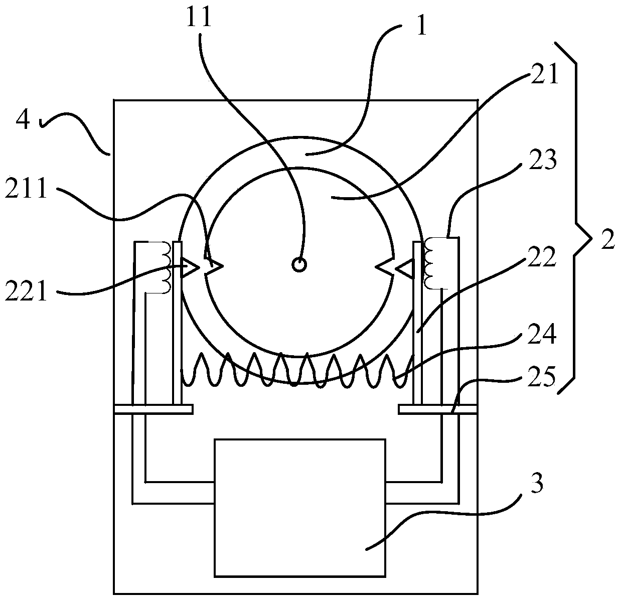
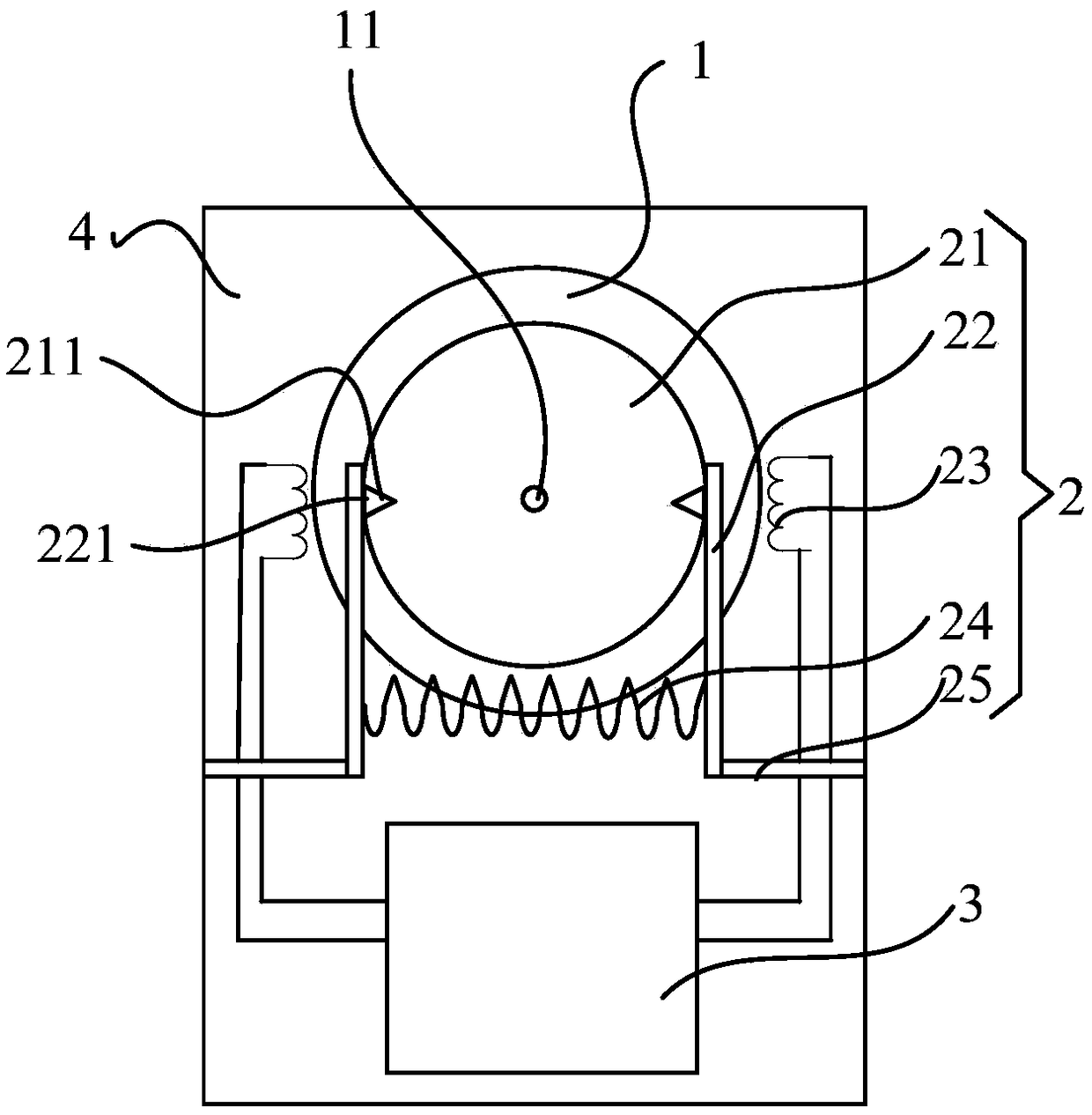
[0034] see Figure 1 ~ Figure 3 As shown, this embodiment provides an implementation of a steering gear, the steering gear includes a motor 1, a reduction gear set (not shown) and a locking structure 2;

[0035] The motor 1 has a rotating shaft 11, and the reduction gear set is connected to the rotating shaft 11 for the reduction output of the motor 1;

[0036] The locking structure 2 is arranged at the position of the rotating shaft 11, and the locking structure 2 is set in linkage with the motor 1; the locking structure 2 limits the movement of the rotating shaft 11 when the motor 1 is in a power-off state turn;

[0037] The locking structure 2 releases the restriction on the rotation of the rotating shaft 11 when the motor 1 is in the energized state.

[0038] A locking structure 2 is provided on the rotating shaft 11 of the motor 1. Through linkage setting, when the motor 1 rotates, the locking structure 2 releases the locking of the rotating shaft 11. When the motor 1 i...

Embodiment 2

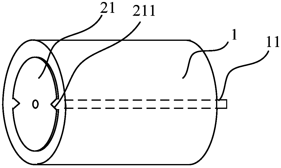
[0058] see Image 6 As shown, this embodiment provides a preferred implementation of the locking structure 2, the locking structure 2 includes a rotating member 21, a limiting member 22 and a coil 23, the center of the rotating member 21 is fixedly connected to the On the rotating shaft 11, the rotating member 21 is provided with a first engaging portion 211, the limiting member 22 is provided with a second engaging portion 221, and the coil 23 is located on the limiting member 22 away from the first engaging portion. On one side of the two engaging parts 221 , and when the steering gear is in a power-off state, there is a displacement gap between the coil 23 and the limiting member 22 .

[0059] In this embodiment, the limiting member 22 is an elastic deformation member, and the elastic deformation member can be made of a ferromagnetic metal material, and the elastic deformation member is in the shape of a curved plate. The end away from the second engaging portion 221 is fi...

Embodiment 3

[0061] see Figure 7 As shown, this embodiment provides a preferred implementation of the locking structure 2, the locking structure 2 includes a rotating member 21, a limiting member 22 and a coil 23, the center of the rotating member 21 is fixedly connected to the On the rotating shaft 11, the rotating member 21 is provided with a first engaging portion 211, and the limiting member 22 is provided with a second engaging portion 221. The limiting member 22 is at least partially made of ferromagnetic material. The coil 23 is located on a side of the limiting member 22 away from the second engaging portion 221 , and when the steering gear is in a power-off state, there is a displacement gap between the coil 23 and the limiting member 22 .

[0062] In this embodiment, the locking structure 2 further includes a support member 26, the support member 26 is fixed on the casing of the motor 1 or the steering gear housing 4, and the limiting member 22 is far away from the first One en...


PUM


Abstract

In order to overcome the problem that the stability of a robot is affected by the rotating of an output shaft, which occurs after the existing steering engine is in a power outage state, the invention provides a steering engine. The steering engine comprises a motor, a speed reducing gear unit and a locking structure, wherein the motor is provided with a rotating shaft, and the speed reducing gear unit is connected with the rotating shaft and used for the speed reducing output of the motor; the locking structure limits the rotating of the rotating shaft when the motor is in the power outage state; and the locking structure relieves limitation on the rotating of the rotating shaft when the motor is in an electrified state. At the same time, the invention further discloses a robot with the steering engine. By adopting the technical scheme, the rotating shaft of the motor can be locked after the steering engine is in the power outage state, and the action keeping of the robot is facilitated.

Description

technical field [0001] The invention belongs to the technical field of motor reduction transmission equipment, and in particular relates to a steering gear and a robot. Background technique [0002] The steering gear is an important component to realize the function of the robot joint, which mainly includes basic components such as a motor, a control circuit board, a reduction gear set, an output shaft, and a sensor. The control method is as follows: setting a control signal, the control signal is transmitted to the motor through the control circuit board, the rotating shaft of the motor is controlled to rotate, and the torque is output through the output shaft after being decelerated by the reduction gear set. After the robot stops moving, the existing steering gear maintains the torque generated by the motor through continuous input current, so that the robot maintains the action when the motion stops. In some cases, such as the robot is powered off and the steering gear i...

Claims


Application Information

Patent Timeline
Patent Type & Authority Patents(China)
IPC IPC(8): B25J17/00
CPCB25J17/00
Inventor 张礼富柳冬熊友军
Owner UBTECH ROBOTICS CORP LTD
Why Eureka
Try Eureka