

Spring bolt overturning self-locking device
A technology of self-locking device and deadbolt, which is applied in the field of locks, can solve the problems of rising processing costs, complicated door lock structure, inconvenient processing of mounting holes, etc., and achieve the effect of reducing processing and installation costs and simple and convenient installation
- Summary
- Abstract
- Description
- Claims
- Application Information
AI Technical Summary
Problems solved by technology
Method used
Image

Examples
Embodiment 1
[0024] Embodiment 1 Lock tongue flipping self-locking device
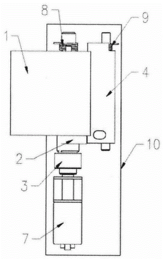
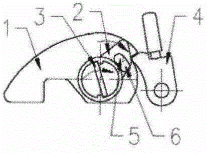
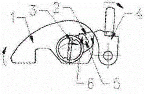
[0025] Such as Figure 1-6 As shown, a deadbolt turning self-locking device includes a deadbolt 1, a first torsion spring 8 for rotating and unlocking the deadbolt, a stopper 4 cooperating with the deadbolt to limit the rotation and unlocking of the deadbolt, and a stopper for rotating to limit the locking of the deadbolt. Rotate the second torsion spring 9 of unlocking, make dead bolt rotate locking and remove block to the restriction of dead bolt to the driving mechanism that dead bolt rotates and unlock, stopper cooperates with the draw-in groove of dead bolt side wall to limit dead bolt to rotate and unlock. The driving mechanism that makes the lock tongue rotate and lock and removes the restriction of the block to the lock tongue to rotate and unlock the lock tongue includes a motor 7 and a cam 2 connected to the motor shaft. The shaft 3 of the motor and the cam 2 are coaxial with the lock tongue 1 Set, betwe...
Embodiment 2
[0029] Embodiment 2 is suitable for casement doors
[0030] Such as Figure 7 As shown, the door frame 13 is fixed on the body of wall 14, Figure 1-6 The shown dead bolt turning self-locking device is installed on the door frame 13. When the swing door 12 is closed, the dead bolt 1 reaches the maximum rotation angle to limit the opening and closing of the door under the drive of the gear reduction motor 7.
[0031] Such as Figure 8 As shown, when the side-hung door 12 needs to be opened, the gear reduction motor 7 drives the dead bolt 1 to rotate until it no longer restricts the opening and closing of the door 12, or the stopper 4 is manually moved to remove its restriction on the dead bolt 1, and the dead bolt 1, that is, it can be rotated under the action of the first torsion spring 8 so that it no longer restricts the opening and closing of the casement door 12.
[0032] In order to avoid the safety of the contact between the side hinged door 12 and the lock tongue 1 a...
Embodiment 3
[0033] Example 3 is suitable for sliding doors
[0034] Such as Figure 9 As shown, will Figure 1-6 The shown lock tongue turning self-locking device is installed on the fixed door 17. Since the lock tongue 1 is a knuckle, it is only necessary to install a lock hook 15 matching the knuckle at the position corresponding to the knuckle of the sliding door 16. The lock tongue 1 is on the gear Driven by the reduction motor 7, the maximum rotation angle is reached, and the lock hook 15 on the sliding door 16 is restricted by the dead bolt 1, so that the sliding door 16 cannot move to the right.
[0035] Such as Figure 10 As shown, when the glass sliding door 16 needs to be opened, the gear reduction motor 7 drives the dead bolt 1 to rotate until it no longer restricts the lock hook 15, or manually moves the stopper 4 to release its restriction on the dead bolt 1, and the dead bolt 1 It can be rotated under the action of the first torsion spring 8 so that it no longer restricts...
PUM
 Abstract
Description
Claims
Application Information