Automatic water retaining panel

A kind of water baffle and automatic baffle technology, applied in dams, flood control panels, water conservancy projects, etc., can solve the problems of high processing cost, low installation efficiency, large panel weight, etc., and achieve reduced processing and installation costs, improved stability, low density effect

Pending Publication Date: 2021-08-24
GUANGZHOU METRO DESIGN & RES INST +1
View PDF2 Cites 0 Cited by
  • Summary
  • Abstract
  • Description
  • Claims
  • Application Information

AI Technical Summary

Problems solved by technology

However, during use, it was found that the panel in the above technology has the following two problems: 1. The structure is complex (four layers), the processing cost is high, and the installation efficiency is low; 2. The panel is heavy, which increases the risk that the water retaining unit cannot float

Method used


Image

  • Automatic water retaining panel
  • Automatic water retaining panel
  • Automatic water retaining panel

Examples


Embodiment 1

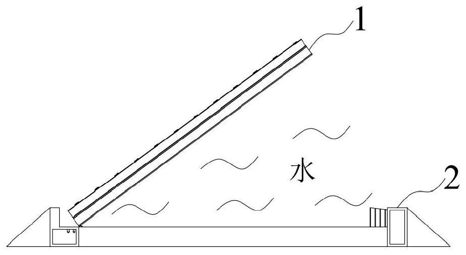
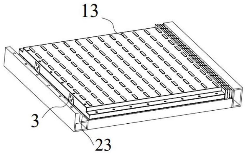
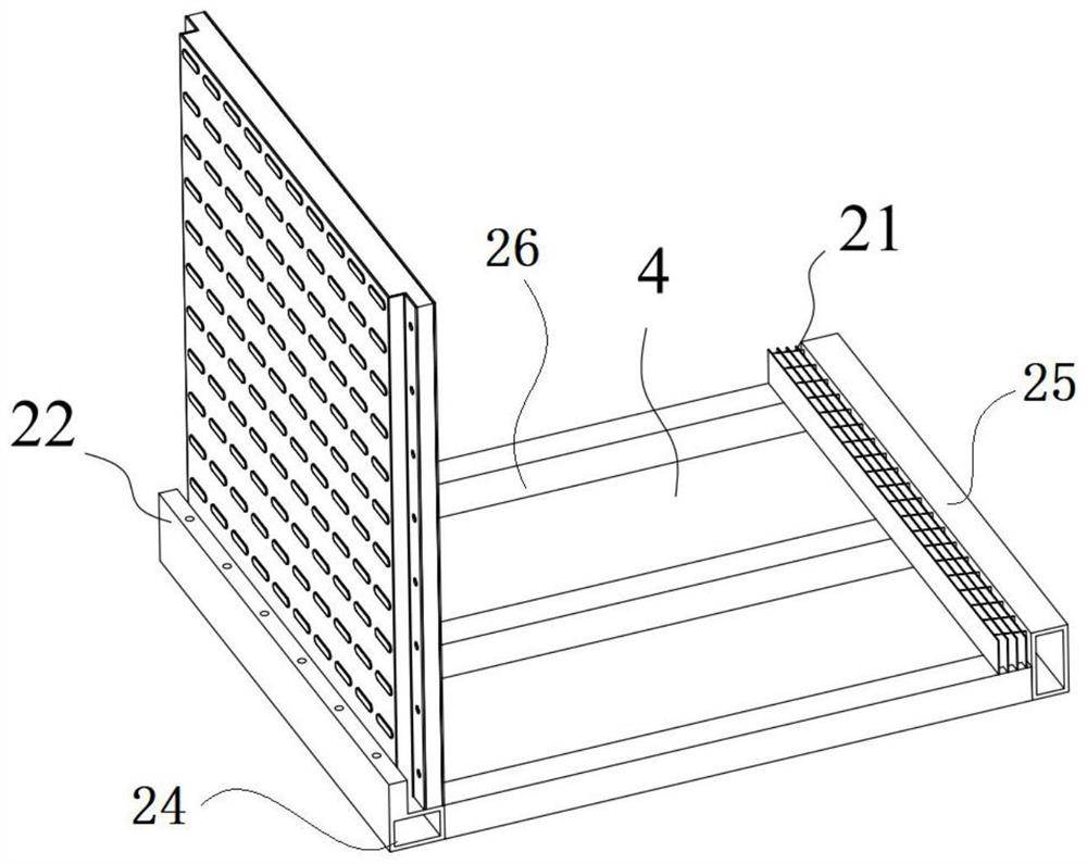
[0031] Embodiment 1: as Figure 1 to Figure 8As shown, according to the embodiment of the present invention, an automatic water retaining panel is provided. The water retaining panel is composed of a plurality of water retaining units sequentially connected. The water retaining unit includes: a base 2, the base 2 includes a water storage chamber 4; Water plate 1, one end of the water retaining plate 1 is hinged with the base 2 through the hinge 3, when the water in the water storage chamber 4 is full, the water retaining plate 1 can rotate around the hinge 3 under the action of buoyancy, thereby playing The function of water retaining; wherein, the adjacent water retaining boards 1 are connected by a connecting mechanism.

[0032] Preferably, the water retaining plate 1 includes a honeycomb core 111, a first outer layer plate 112 and a second outer layer plate 113; the first outer layer plate 112 is connected to the upper surface of the honeycomb core 111, and the second outer...

Embodiment 2

[0042] Such as Figure 9 As shown, the difference between this embodiment and Embodiment 1 is that the connecting mechanism includes a connecting piece 8, a third sealing strip 63 and a third screw 93, and the connecting piece 8 is symmetrically provided with two second installation grooves; The ends of the water retaining plate 1 honeycomb core 111 at the junction of the two water retaining units are integrally formed with mounting bosses 12, and the mounting bosses 12 of the two adjacent water retaining plates 1 honeycomb cores 111 respectively extend into two second In the installation groove, two third sealing strips 63 are arranged symmetrically outside the upper end and the lower end of the installation boss 12, and the third sealing strip 63 is located between the connector 8 and the water retaining plate 1, and the installation boss 12 and the third seal The strip 63 can completely fill the second installation groove; the third screw hole is symmetrically provided on t...


PUM

PropertyMeasurementUnit
Densityaaaaaaaaaa
Densityaaaaaaaaaa

Abstract

The invention provides an automatic water retaining panel, and relates to the technical field of flood control equipment. The water retaining panel is used for retaining water for an entrance and exit of an underground building, and the water retaining panel is formed in a way that a plurality of water retaining units are connected in sequence; each water retaining unit comprises a base and a water baffle, wherein the base comprises a water storage cavity, one end of the water baffle is hinged to the base through a hinged piece, and when the water storage cavity is full of water, the water baffle can rotate around the hinged piece under the action of buoyancy; and the adjacent water baffles are connected by connecting mechanisms. According to the automatic water retaining panel, an integrated aluminum honeycomb panel is adopted, the number of structures is small, the machining and mounting cost is greatly reduced, secondly, in order to enable the water retaining panel to float when meeting water and to bear passing of vehicles when the water retaining panel is closed, the panel is required to have the properties of small density and high pressure resistance, a honeycomb core of the automatic water retaining panel has the two properties at the same time, and compared with a multilayer composite panel, the stability of the honeycomb core is greatly increased.

Description

technical field [0001] The invention relates to the technical field of flood control equipment, in particular to an automatic water retaining panel. Background technique [0002] Since short-term heavy rain may cause urban waterlogging, isolating rainwater outside the subway and underground garage is an effective measure to prevent vehicles from being flooded and causing property damage. [0003] The Chinese patent application No. 201120394634.1 proposes a flood control panel for an underground garage, which includes a plurality of floating barrel chambers arranged at intervals along the road width direction and a water storage tank corresponding to the floating barrel chambers. When the structure is sunny or the amount of rain is small, the water retaining board is placed horizontally on the same level as the ordinary road. As the rainfall increases, it will automatically play the role of retaining water, but it is necessary to set up a floating bucket room, a storage tank,...

Claims


Application Information

Patent Timeline
IPC IPC(8): E02B3/10E06B9/00
CPCE02B3/10E02B3/104E06B9/00E06B2009/007
Inventor 胡圣伟范良凯解峰倪洋熊科王开玉贾彦明陈家乐曾程亮卢佳宾王博王阳明张德军张伟赵俊龙刘军舰刘首崔艳斌陶涛郭浩马小娇
Owner GUANGZHOU METRO DESIGN & RES INST
Why Eureka
Try Eureka