Gas injector with improved sealing

A technology of gas injectors and sealing components, applied in fuel injection devices, special fuel injection devices, combustion engines, etc., to achieve the effect of simple cost, good sealing and improved sealing

Active Publication Date: 2017-02-01
ROBERT BOSCH GMBH
View PDF7 Cites 0 Cited by
  • Summary
  • Abstract
  • Description
  • Claims
  • Application Information

AI Technical Summary

Problems solved by technology

This can lead to undesired problems in the gas injector and / or in the engine compartment, since the gaseous medium can be ignited

Method used


Image

  • Gas injector with improved sealing
  • Gas injector with improved sealing
  • Gas injector with improved sealing

Examples


Embodiment Construction

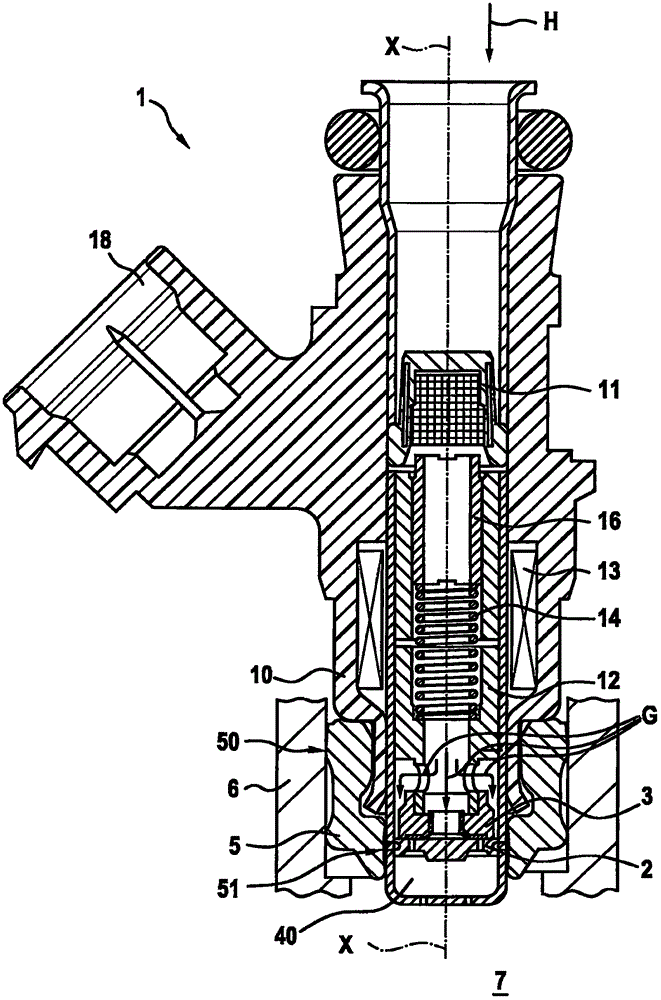
[0019] Refer to the attached Figures 1 to 3 The gas injector 1 according to a preferred embodiment of the present invention will be described in detail.

[0020] The gas injector 1 of this embodiment is arranged on the intake pipe 7 and is used to blow gaseous fuel into said intake pipe. Alternatively, the gas injector can also blow directly into the combustion chamber.

[0021] The gas injector 1 comprises a valve housing 10 , a solenoid armature 12 , a solenoid coil 13 and a closing spring 14 . An adjustment pin 16 is provided to adjust the return force of the closing spring 14 . Gas is supplied along the axis X-X of the gas injector (arrow H) and is guided through the filter 11 . The solenoid coil 13 is fixed on the valve housing 10 . The electrical plug connector 18 is arranged laterally on the gas injector.

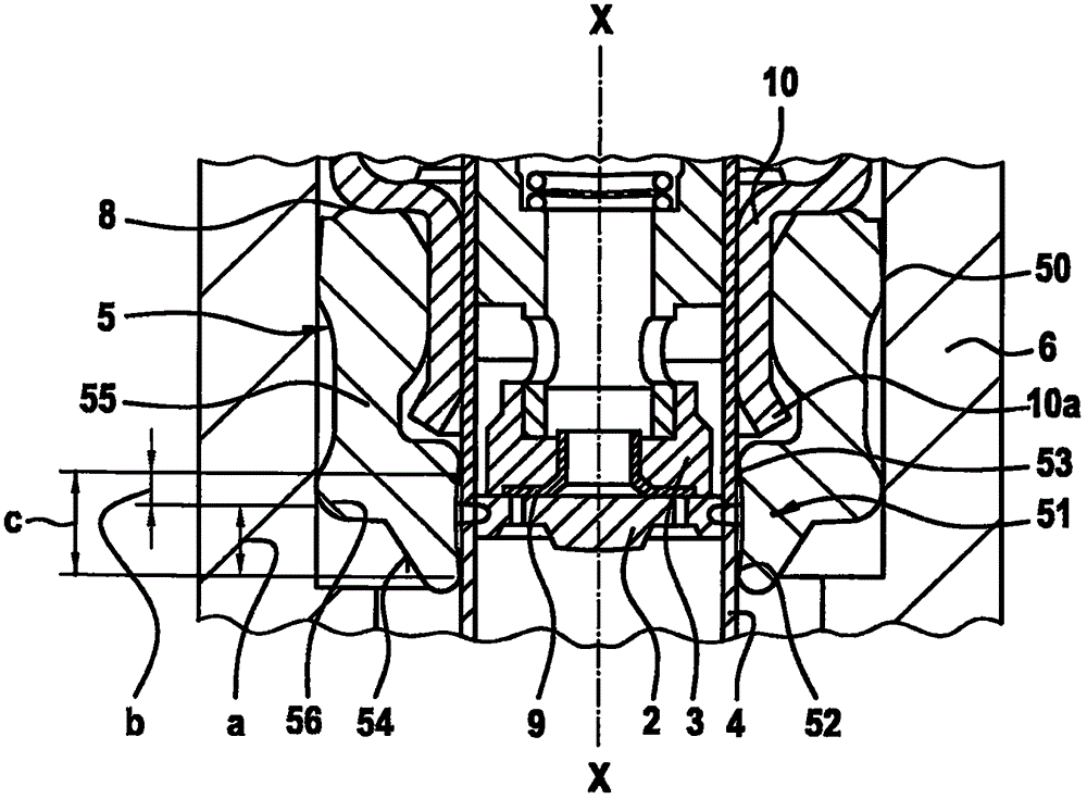
[0022] Fastened to one axial end of the magnetic armature 12 is a closing element 3 on which an elastomeric sealing element 9 is arranged. The closing element...


PUM


Abstract

The invention relates to a gas injector for injecting a gaseous medium, comprising a sealing element (5) which is arranged on an outer surface of an outer component (4, 10) of the gas injector, the sealing element (5) being arranged for sealing between the outer surface and an internal combustion engine receiving element (6). The sealing element (5) has an outer sealing geometry (50) for sealing on the receiving element (6) and an inner sealing geometry (51) for sealing on the outer surface of the gas injector, and wherein the sealing element (5) has a support area (56), which is arranged on the outer circumference of the sealing element (5) opposite to the inner sealing geometry (51) and is spaced apart from the outer sealing geometry in the axial direction (X-X).

Description

technical field [0001] The invention relates to a gas injector for blowing into a gaseous medium, which has improved tightness, in particular tightness inside the injector and in the installed state with respect to the engine compartment, and also relates to a A gas internal combustion engine, in particular a gas internal combustion engine with a turbocharger. Background technique [0002] The prior art discloses different configurations of gas injectors. Such a gas injector is known, for example, from DE 10 2013 202 631 A1. The sealing of the gas injector relative to components of the internal combustion engine, such as the cylinder head, is achieved here by means of an O-ring. Such an injector is shown, for example, in FIG. 4 . The disclosed gas injector 1 comprises a closing element 3 which seals against the sealing seat 2 . The O-ring 15 seals the gas injector 1 relative to the cylinder head 6 . Due to the use of the turbocharger, the pressure in the area 7 upstream...

Claims


Application Information

Patent Timeline
Patent Type & Authority Applications(China)
IPC IPC(8): F02M21/02
CPCF02M21/0266F02M2200/16F02M21/0212F02M21/0254F02M21/0278F16K1/34F16K31/0651Y02T10/30
Inventor E·奥克伦特F·米勒
Owner ROBERT BOSCH GMBH
Why Eureka
Try Eureka