Noise filter installation structure
A noise filter and construction technology, applied in the direction of inductors, fixed inductors, electrical component structure associations, etc., can solve the problems of signal waveform deformation, difficult data transfer, etc., and achieve the purpose of suppressing the transmission of common mode noise and preventing electrostatic damage Effect
Active Publication Date: 2018-06-26
MURATA MFG CO LTD
View PDF6 Cites 0 Cited by
- Summary
- Abstract
- Description
- Claims
- Application Information
AI Technical Summary
Problems solved by technology
Therefore, if an existing common mode choke coil is inserted into each group of two wires selected from the three wires, the signal waveform will be deformed
As a result, normal data transfer is difficult
Method used
View moreImage
Smart ImageViewing Examples
Examples
Embodiment 3
[0058] In Example 3, also in the same manner as in Example 2, electrostatic destruction of the first component 11 and the second component 12 can be prevented. In addition, since the electrostatic discharge protection structures 26A, 26B, and 26C are incorporated in the common mode choke coil 20, the number of components and the mounting area can be reduced.
Login to View More PUM
 Abstract
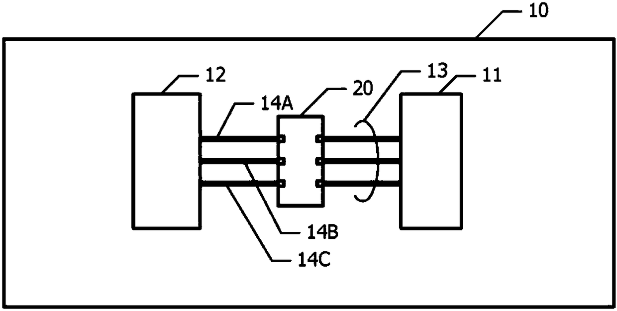
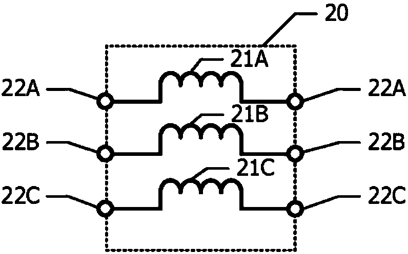
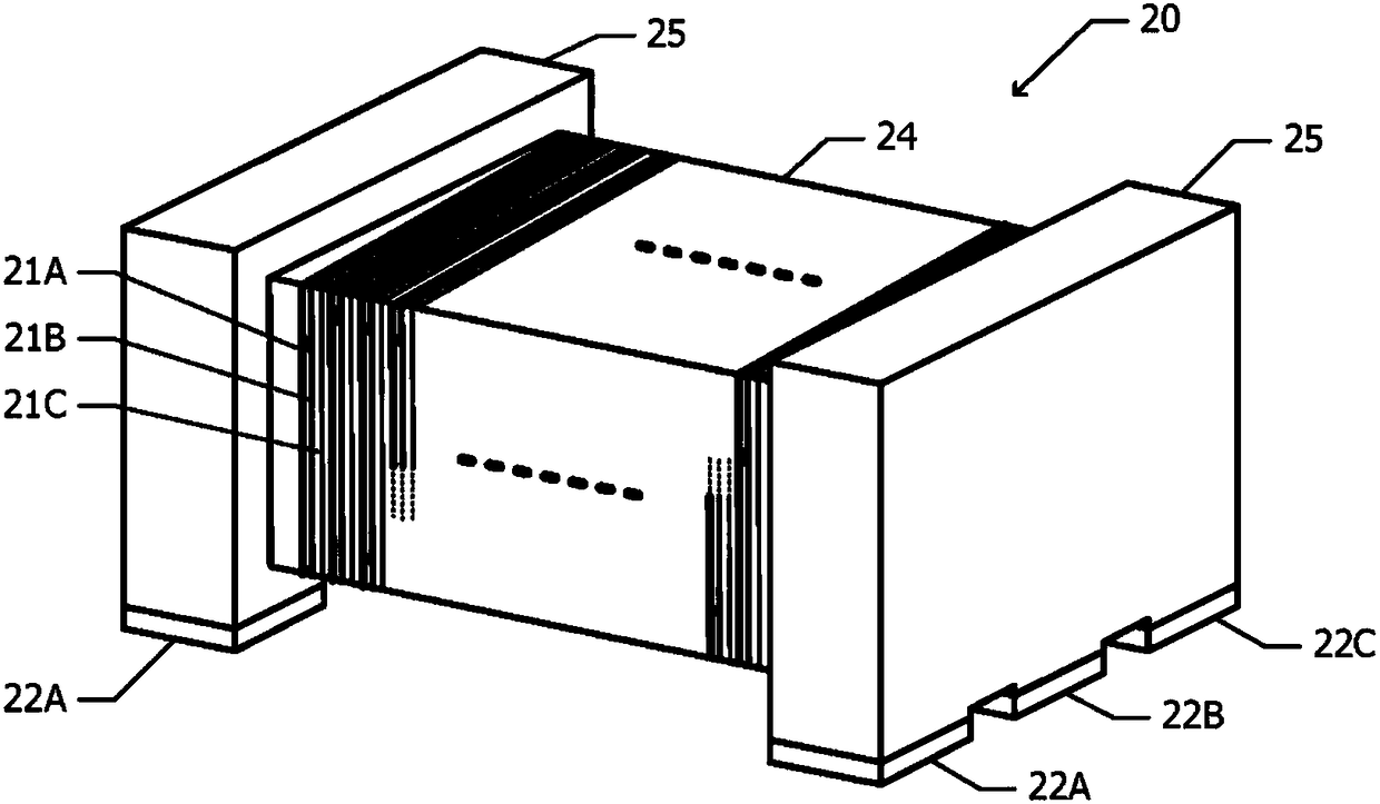
The present invention provides a noise filter mounting structure capable of effectively removing common-mode noise of a transmission line including three wires. The transmission line includes three wires formed on the substrate. Each wire carries a signal of three valued levels. A common mode choke coil is inserted in the transmission line. The common mode choke coil includes three coils coupled to each other and three pairs of external electrodes respectively connected to both ends of the respective coils. The external electrodes of the common mode choke coil are connected to the transmission line by inserting the three coils in series with the three wires.
Description
technical field [0001] The present invention relates to a noise filter mounting structure for removing common mode noise. Background technique [0002] The mipi D-PHY specification is defined as a signal interface between integrated circuit elements in mobile devices and display and camera modules. In the D-PHY standard, a differential transmission method is used in which signals transmitted on two wires have a mutual anti-phase relationship. A common mode choke coil is used as a noise filter for removing common mode noise in a transmission line using a differential transmission method, which hardly affects the transmitted signal. The common mode choke consists of two coils coupled to each other. The two coils are respectively inserted into the two wires in series. [0003] Non-Patent Document 1: mipi D-PHY Specification v1.2 (http: / / mipi.org / specifications / physical-layer#D-PHY Specification) [0004] In recent years, a transmission method with three wires (mipi C-PHY sp...
Claims
Login to View More Application Information
Patent Timeline
 Patent Type & Authority Patents(China)
IPC IPC(8): H01F17/04H01F27/28H01F27/29H01F27/30H01F27/40
CPCH01F17/04H01F27/28H01F27/2823H01F27/292H01F27/306H01F27/40H01F2027/408H03H7/427H01F2017/0093H01F27/29H01F27/402
Inventor 孝山康太今西由浩宇田真悟
Owner MURATA MFG CO LTD
Features
- R&D
- Intellectual Property
- Life Sciences
- Materials
- Tech Scout
- Unparalleled Data Quality
- Higher Quality Content
- 60% Fewer Hallucinations
Learn More Browse by: Latest US Patents, China's latest patents, Technical Efficacy Thesaurus, Application Domain, Technology Topic, Popular Technical Reports.
© 2025 PatSnap. All rights reserved.Legal|Privacy policy|Modern Slavery Act Transparency Statement|Sitemap|About US| Contact US: help@patsnap.com


