Wire locking terminal with torsional spring

A wire-lock terminal and torsion spring technology, applied in the field of wire-lock terminals, can solve problems such as installation troubles, time-consuming, and laborious problems, and achieve the effects of flexible and convenient layout, quick and convenient use, and low installation cost

Active Publication Date: 2017-02-01
SHANGHAI AEROSPACE SCI & IND ELECTRIC APPLIANCE RES INST
View PDF7 Cites 4 Cited by
  • Summary
  • Abstract
  • Description
  • Claims
  • Application Information

AI Technical Summary

Problems solved by technology

This is time-consuming and labor-intensive, which increases the installation cost and difficulty of the user, and brings great trouble to the installation.
Unable to meet the needs of customers for fast, convenient, safe and efficient installation

Method used


Image

  • Wire locking terminal with torsional spring
  • Wire locking terminal with torsional spring
  • Wire locking terminal with torsional spring

Examples


Embodiment

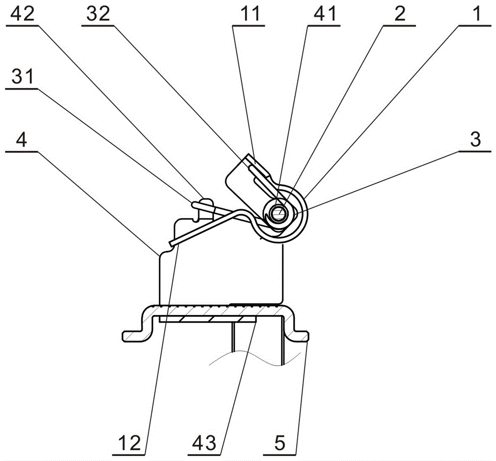
[0026] refer to figure 1 , Figure 5 , The present invention is used in conjunction with the switch cabinet. There are several locking wire terminal blocks inside the switch cabinet, and the corresponding locking wire terminal blocks are provided with safety buttons 6 . When in use, the present invention is inserted into the corresponding locking wire terminal base as required, and when the wire to be connected is plugged into the present invention, the purpose of quick wire locking can be realized.

[0027] Below in conjunction with the embodiment of the present invention and accompanying drawing, the working process of the present invention is further described as follows:

[0028] Wire from insertion to locking process

[0029] refer to figure 1 , figure 2 , image 3 , Figure 4 , Figure 5 According to the design requirements of the switch cabinet, the present invention is installed in the corresponding lock wire terminal block of the switch cabinet, and the wire s...


PUM


Abstract

The invention discloses a wire locking terminal with a torsional spring. The wire locking terminal comprises a spring sheet, a rotating shaft, the torsional spring, a shell and a terminal. The wire locking terminal capable of quickly locking a wire is formed by using the structure of the spring sheet, the torsional spring, the shell and the terminal. The wire locking terminal is matched with a switch cabinet for use, and has the advantages of being simple in structure, flexible and convenient to arrange, low in installation cost, quick and convenient to use, safe and reliable.

Description

technical field [0001] The invention relates to a wire locking terminal in the technical field of electrical connectors, in particular to a wire locking terminal with a torsion spring. Background technique [0002] Quick lock wire terminal block is an important part for connecting wires in electronic equipment. Its high installation efficiency is unsurpassed by other lock wire structures. The terminal blocks commonly used in the market are all locked by screws. The user first needs to use a tool to open the screw on the terminal block, then put the wire or OT terminal into the terminal block, and finally tighten the previously loosened screw to fix the wire. This is time-consuming and labor-intensive, which increases the installation cost and difficulty of the user, and brings great trouble to the installation. It cannot meet the needs of customers for fast, convenient, safe and efficient installation. Based on this status quo, it is imminent to design a fast thread locki...

Claims


Application Information

Patent Timeline
Patent Type & Authority Applications(China)
IPC IPC(8): H01R4/48
CPCH01R4/4863
Inventor 张翔王宏吉
Owner SHANGHAI AEROSPACE SCI & IND ELECTRIC APPLIANCE RES INST
Why Eureka
Try Eureka