Stator iron core, stator, motor and preparation method for stator iron core

A stator core and iron core technology, applied in the direction of electrical components, electromechanical devices, electric components, etc., can solve the problem of large cogging torque, etc., and achieve the effect of low cogging torque and high-precision positioning

Inactive Publication Date: 2017-02-01
GREE ELECTRIC APPLIANCES INC +1
View PDF7 Cites 0 Cited by
  • Summary
  • Abstract
  • Description
  • Claims
  • Application Information

AI Technical Summary

Problems solved by technology

This results in a l

Method used


Image

  • Stator iron core, stator, motor and preparation method for stator iron core
  • Stator iron core, stator, motor and preparation method for stator iron core
  • Stator iron core, stator, motor and preparation method for stator iron core

Examples


Embodiment Construction

[0035] The present invention will be described in detail below with reference to the accompanying drawings and examples.

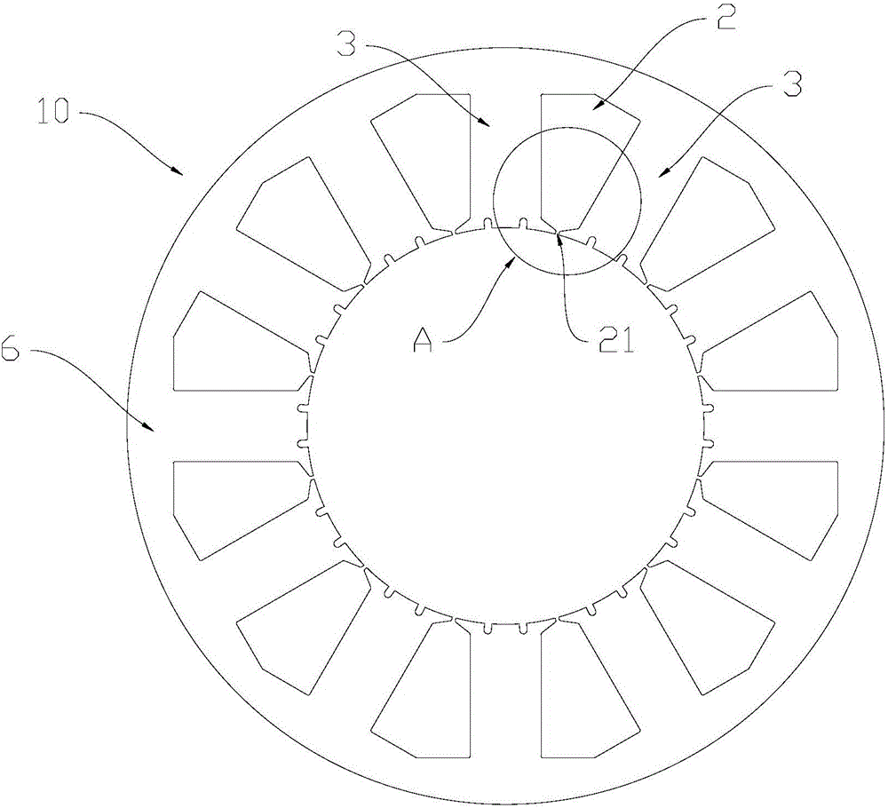
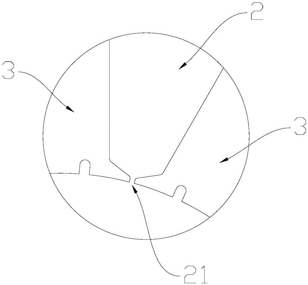
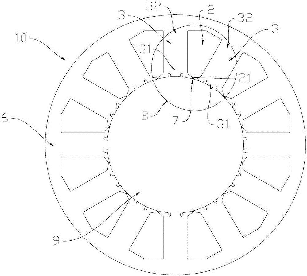
[0036] refer to Figure 3 to Figure 6 As shown, the stator core 10 according to the present invention includes a body 1 and a plurality of stator slots 2 arranged on the body 1 . A plurality of said stator slots 2 are arranged along the circumferential direction. Each of said stator slots 2 has a notch 21 . A magnetic conduction part is provided at the notch 21 of the stator slot 2 .

[0037] The magnetically permeable part can reduce or even close the notch 21 of the stator slot 2, so that even the magnetic permeability of the magnetic field at the notch 21 can be consistent with that of the stator teeth 3, thereby reducing the cogging torque. For example, through simulation calculations, refer to Figure 7 and Figure 8 Shown, under the same test condition, the cogging torque value of the servomotor in the prior art is 139.64mN. Part) the cogging t...


PUM


Abstract

The invention provides a stator iron core, a stator, a motor and a preparation method for the stator iron core. The stator iron core comprises a body and multiple stator grooves, wherein the multiple stator grooves are formed in the body; the multiple stator grooves are arranged in a circumferential direction; each stator groove has a groove opening; and a magnetic conducting part is arranged at the groove opening of at least one stator groove. According to the stator iron core, the stator, the motor and the preparation method for the stator iron core, the advantages as follows are achieved: the motor comprising the stator iron core provided by the invention has relatively low cogging torque; high-precision positioning of the motor can be promoted; the low-speed performance of the motor in a speed control system also can be facilitated; and the smooth and stable running of the motor also can be realized.

Description

technical field [0001] The invention relates to the technical field of motors, in particular to a stator core, a stator, a motor and a method for preparing the stator core. Background technique [0002] For servo motors, cogging torque is an important parameter that affects positioning accuracy. Cogging torque is the torque generated by the interaction between the permanent magnet and the stator core when the winding of the permanent magnet motor is not energized, and is caused by the tangential component of the interaction force between the permanent magnet and the armature teeth. The influence of cogging torque on the motor is various. For example, the cogging torque may affect the high-precision positioning of the motor in the position control system, and may also affect the low-speed performance of the motor in the speed control system. As another example, the cogging torque may also make the motor torque fluctuate, so that the motor cannot run smoothly. Contents of ...

Claims


Application Information

Patent Timeline
IPC IPC(8): H02K1/16H02K3/493
CPCH02K1/16H02K3/493
Inventor 郝福刚李昊赵正肖胜宇钟成堡
Owner GREE ELECTRIC APPLIANCES INC
Why Eureka
Try Eureka