Visible light communication-based device and method for LED light source

A technology of LED light source and optical signal, applied in the field of visible light communication, can solve problems such as complex implementation process

Inactive Publication Date: 2017-02-01
MIDEA SMART TECH CO LTD
View PDF6 Cites 5 Cited by
  • Summary
  • Abstract
  • Description
  • Claims
  • Application Information

AI Technical Summary

Problems solved by technology

Although this technical solution can realize the driving of the LED light source based on the indoor positioning system, it is actually to drive the flicker frequency of the LED light source by adding a pulse width modulation signal, and the implementation process is relatively complicated.

Method used


Image

  • Visible light communication-based device and method for LED light source
  • Visible light communication-based device and method for LED light source
  • Visible light communication-based device and method for LED light source

Examples


Embodiment Construction

[0035] The specific implementation manners of the embodiments of the present invention will be described in detail below in conjunction with the accompanying drawings. It should be understood that the specific implementation manners described here are only used to illustrate and explain the embodiments of the present invention, and are not intended to limit the embodiments of the present invention.

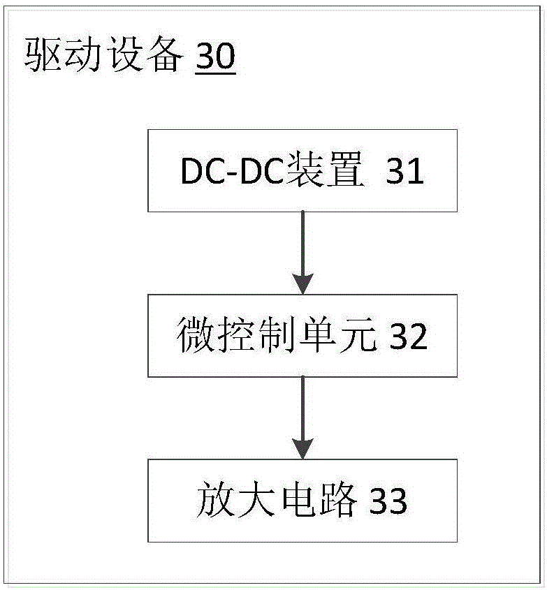
[0036] image 3 A schematic structural diagram of a driving device for an LED light source in an embodiment is shown. Such as image 3As shown, the embodiment of the present invention provides a driving device 30 for an LED light source, and the driving device 30 may include: a DC-DC device 31 for stepping down the received voltage to provide a micro control unit required voltage; the micro-control unit 32 is used to encode the positioning information related to the LED light source stored in the micro-control unit to generate a positioning data frame; and an amplifying circuit ...


PUM


Abstract

Embodiments of the present invention provide a visible light communication-based device and method for an LED light source, belonging to the field of visible light communication. The drive device for the LED light source may comprise a DC-DC apparatus, a micro-control unit, and an amplification circuit. The DC-DC apparatus is used for lowering a received voltage so as to provide a demanded voltage for the micro-control unit. The micro-control unit is used for encoding positioning information related to the LED light source and stored in the micro-control unit so as to generate a positioning data frame. The amplification circuit is used for amplifying the positioning data frame, and outputting the amplified positioning data frame to the LED light source to drive the LED light source. The positioning information is set in the drive device of the LED light source, and the drive device encodes the positioning information and amplifies the positioning data frame so as to drive the LED light source, so that the visible light emitted by the LED light source carries position information, therefore, indoor positioning is realized easily.

Description

technical field [0001] The present invention relates to the field of visible light communication, in particular, to a device and method for LED light sources based on visible light communication. Background technique [0002] With the development of social economy, the requirements for positioning technology are not limited to outdoors, and indoor positioning technology has become a research hotspot in recent years. In large supermarkets, hospitals, schools and other occasions, the use of indoor positioning technology can quickly find the target and its location, so as to achieve reliable indoor navigation. In past studies, researchers have proposed many indoor positioning schemes based on radio wave technology. Mainly include radio frequency identification, WIFI, ultrasound system, bluetooth and so on. However, the indoor positioning system of wireless communication will be affected by electromagnetic interference, and the communication quality will decrease when shared b...

Claims


Application Information

Patent Timeline
Patent Type & Authority Applications(China)
IPC IPC(8): H04B10/116H04B10/50
CPCH04B10/116H04B10/502
Inventor 范林勇
Owner MIDEA SMART TECH CO LTD
Why Eureka
Try Eureka