Discharging device for semi-autogenous mill

A technology of semi-autogenous mill and discharge device, which is applied in the direction of grain processing, etc. It can solve the problems of broken grating plate fixing bolts, insufficient impact resistance, and prolonged downtime, so as to maintain stability and fluency, and improve follow-up replacement Efficiency, the effect of enriching the range of material selection

Active Publication Date: 2017-02-08
CITIC HEAVY INDUSTRIES CO LTD +1
View PDF7 Cites 1 Cited by
  • Summary
  • Abstract
  • Description
  • Claims
  • Application Information

AI Technical Summary

Problems solved by technology

[0002] The discharge dustpan plate of the semi-autogenous mill is used as a forced discharge device for pulp. In addition to protecting the discharge end cover from wear, it also supports the grid plate stacked on it. Therefore, the dustpan plate is required to be wear-resistant and durable. Good impact resistance and rigidity, if the impact resistance is insufficient, it is easy to cause the dustpan plate to break due to the impact of steel balls on the grid plate, and the lack of rigidity will cause the grid plate to shake during the operation of the mill, resulting in frequent grating plate fixing bolts. fracture
[0003] At present, the commonly used dustpan plate material is wear-resistant alloy cast steel. This kind of discharge dustpan plate has a heavy weight, which causes the weight of the discharge end of the mill to be much greater than that of the feed end, and the production cost is high.
When changing the liner of a large mill, the steel balls and materials in the mill will not be discharged, but the operation method is adopted, and the operation position of changing the liner is located at the side of the mill, which causes the dustpan board to be installed When using the grid plate, due to the heavy weight, the bolt holes of the dustpan plate and the bolt holes of the end cover are misaligned, and the fixing bolts of the grid plate and the groove plate are in contact with the bolt holes of the end cover. The bolts of the grid plate will always contact and rub against the bolt holes of the end cover, which not only damages the bolt holes of the end cover, but also makes it impossible to pull out the bolts when disassembling the grid plate. Extracting bolts adds a lot of unnecessary work and prolongs downtime

Method used


Image

  • Discharging device for semi-autogenous mill
  • Discharging device for semi-autogenous mill
  • Discharging device for semi-autogenous mill

Examples


Embodiment Construction

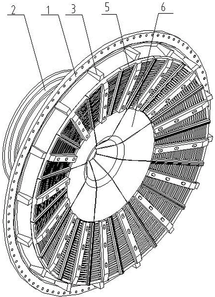
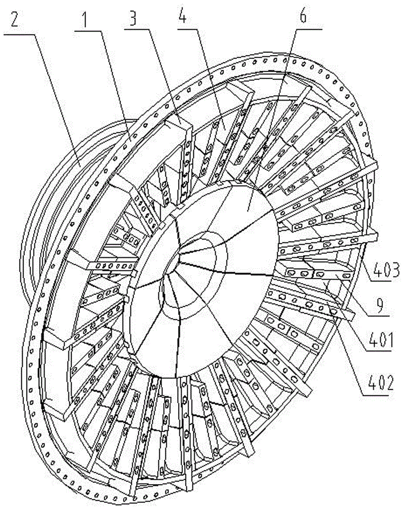
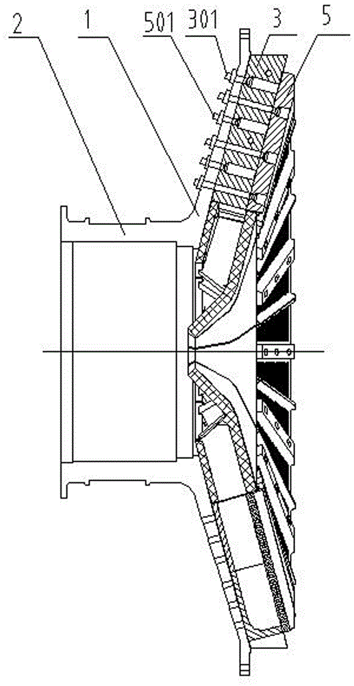
[0026] Such as figure 1 Only Figure 6 As shown, a semi-autogenous mill discharge device of the present invention includes a conical end cover 1 of the barrel of the semi-autogenous mill and a discharge pipe 2 arranged in the middle of the outer side of the end cover 1, and the inner side of the end cover 1 On the end surface of the second flat-head bolt 301, a plurality of support plates 3 for fixing the fan-shaped lattice board 5 are fixedly arranged with the center of the end cover 1 as the center and evenly spaced radially, and the second flat-head bolt 301 The nut is located on the side of the end cover 1 where the discharge pipe 2 is arranged, which is convenient for disassembly and assembly. The bolt head is arranged in the groove on the support plate 3. The selection of flat head bolts can make no gap between the support plate 3 and the fan-shaped grid plate 5. The support plate 3 is also provided with a through hole 302 and a second lifting hole 303 for installing th...


PUM


Abstract

The invention relates to the technical field of semi-autogenous mills and discloses a discharging device for a semi-autogenous mill. The discharging device for the semi-autogenous mill comprises a semi-autogenous mill end cover and a discharging pipe; supporting plates which are uniformly distributed at an interval in a radial shape by taking the circle center of the end cover as the center are arranged at the inner side of the end cover; a winnowing fan plate is arranged between any two supporting plates; each winnowing fan plate comprises a near fan-shaped lining plate, a branch side plate and a circular arc-shaped lining plate; the end face of the fixed end, far away from the end cover, of the supporting plate is provided with a fan-shaped grid plate; a flow guide plate is arranged at the end part of an inner ring of each fan-shaped grid plate; a plurality of fan-shaped grid plates together form an annular grid plate; the cavity between the annular grid plate and the winnowing fan plates forms an ore pulp accommodating chamber; a plurality of flow guide plates together form a central discharging trough plate which communicates with the ore pulp accommodating chamber and the discharging pipe. The discharging device for the semi-autogenous mill has the advantages of overcoming the problem that a master discharging grid plate in the prior art is quite difficult to dismount, shortening the construction period for replacing the lining plates, widening the range of materials selected by the discharging winnowing fan plates, and lowering the production cost.

Description

technical field [0001] The invention relates to the technical field of semi-autogenous mills, in particular to a semi-autogenous mill discharge device. Background technique [0002] The discharge dustpan plate of the semi-autogenous mill is used as a forced discharge device for pulp. In addition to protecting the discharge end cover from wear, it also supports the grid plate stacked on it. Therefore, the dustpan plate is required to be wear-resistant and durable. Good impact resistance and rigidity, if the impact resistance is insufficient, it is easy to cause the dustpan plate to break due to the impact of steel balls on the grid plate, and the lack of rigidity will cause the grid plate to shake during the operation of the mill, resulting in frequent grating plate fixing bolts. fracture. [0003] At present, the commonly used dustpan plate material is wear-resistant alloy cast steel. This kind of discharge dustpan plate has a heavy weight, which causes the self-weight of t...

Claims


Application Information

Patent Timeline
IPC IPC(8): B02C17/18B02C17/22
CPCB02C17/183B02C17/22B02C17/1855
Inventor 王炳龙韩春阳和蕴锋任亚楠高祖瑞高志明吴钧宇李超张振华刘建平赵魏倪小令
Owner CITIC HEAVY INDUSTRIES CO LTD
Why Eureka
Try Eureka