Automobile body correcting system

A technology for calibrating system and car body, applied in the field of automobiles, can solve the problems of inconvenient installation and disassembly, multi-manpower, material resources and time, occupying too much working space, etc., to avoid installation and disassembly, the overall structure is simple, and the utilization rate is improved. Effect

Active Publication Date: 2017-02-08
NANJING WOYU MECHANICAL & ELECTRICAL EQUIP CO LTD
View PDF6 Cites 3 Cited by
  • Summary
  • Abstract
  • Description
  • Claims
  • Application Information

AI Technical Summary

Problems solved by technology

[0003] The current car body correction machine has a complex structure. When correcting the car body, the car must first be fixed on the correction platform or frame. Since many accident cars cannot start and drive by themselves, it is necessary to use a forklift or a crane to move the car to the correction platform. platform or frame, and then fix it, so a lot of manpower, material resources and time are needed. At the same time, the existing fixing method is to fix the car on the correction platform or frame through multiple clamps, which are separated from the correction platform or frame. Body structure, multiple fixtures need to be installed and disassembled during each calibration process, and the fixture itself is very heavy, which is very inconvenient to install and disassemble, which virtually increases the time for vehicle body calibration and the workload of operators. Moreover, At present, the stretching systems such as hydraulic stretching columns or mechanical stretching devices on the car body correction machine are connected and fixed with the correction platform or frame. Body correction takes up too much workspace

Method used


Image

  • Automobile body correcting system
  • Automobile body correcting system
  • Automobile body correcting system

Examples


Embodiment Construction

[0022] The present invention will be described in detail below in conjunction with the accompanying drawings.

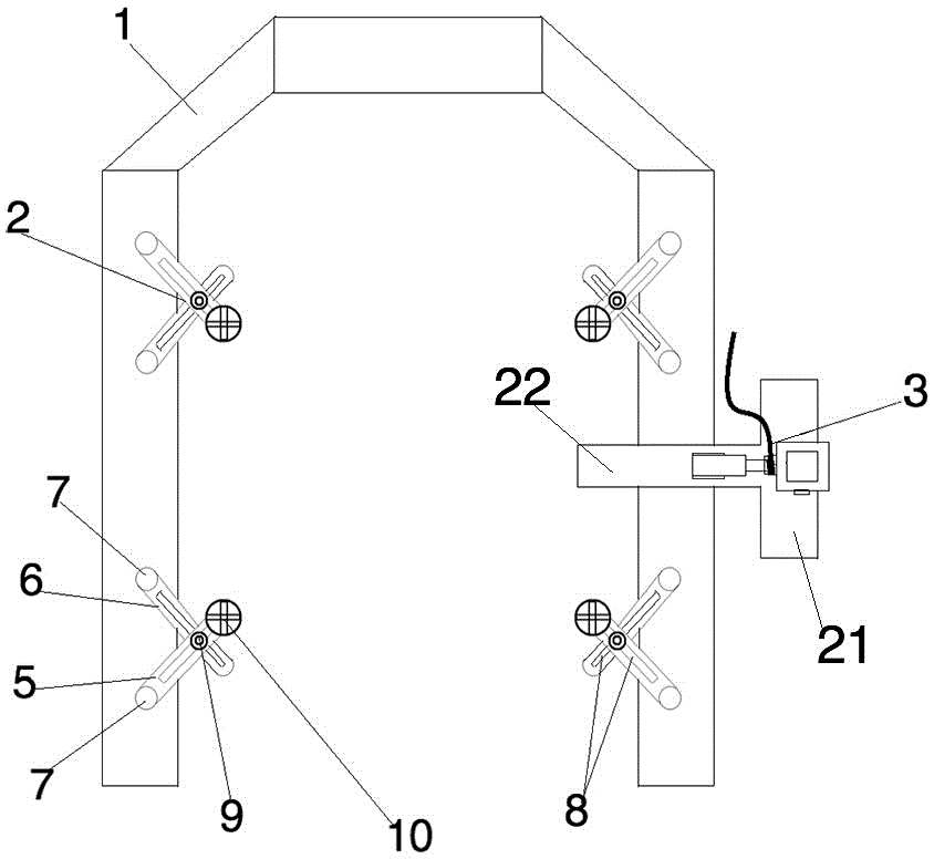
[0023] figure 1 It is a schematic diagram of the overall structure of the present invention;

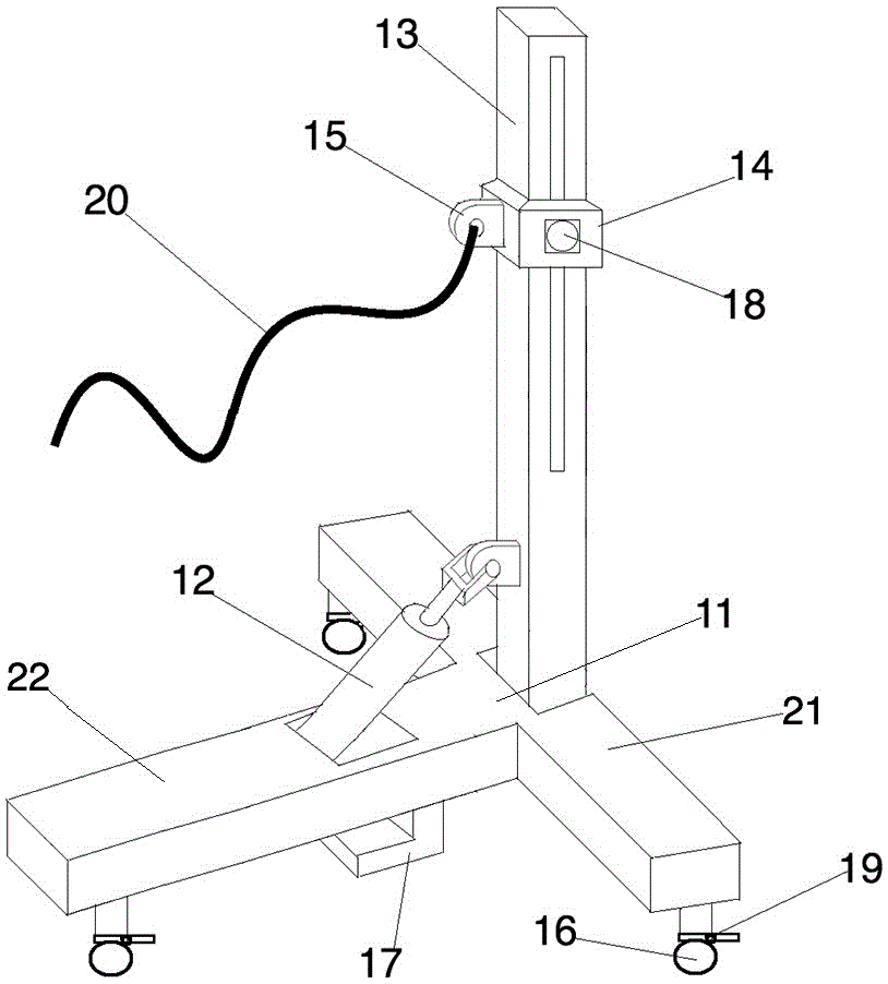
[0024] figure 2 It is a structural schematic diagram of the hydraulic stretching column of the present invention;

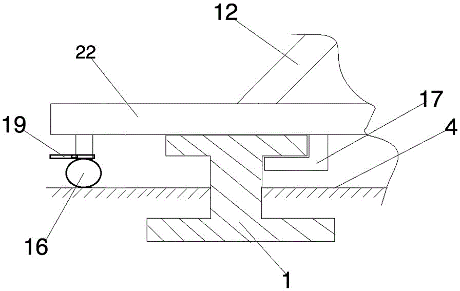
[0025] image 3 It is a schematic diagram of the connection between the hydraulic stretching column and the correction platform frame of the present invention;

[0026] Such as Figure 1-3 As shown: this embodiment is a vehicle body correction system, including a correction platform frame 1, a clamp 2, and a hydraulic stretching column 3, wherein the correction platform frame 1 is U-shaped, and its top is set above the ground 4, and the bottom Then it is buried below the ground 4, and the cross-sectional shape of the correction platform frame 1 is I-shaped, which has the advantages of good structural stability, high compression resistance, tensile streng...


PUM


Abstract

The invention discloses an automobile body correcting system. The automobile body correcting system comprises a correcting platform framework, a clamp and a hydraulic stretching column, wherein the correcting platform framework is U-shaped, the clamp comprises a fixing rod and a locating rod which are arranged in a crossed manner, the hydraulic stretching column comprises a T-shaped base, a hydraulic oil cylinder, a stretching column and a stretching slider, the T-shaped base comprises a transverse arm and a longitudinal arm, the longitudinal arm is arranged on the correcting platform framework in a crossing manner and is connected with the correcting platform framework through a framework connector arranged at the bottom of the longitudinal arm, the stretching column is vertically arranged in the middle of the transverse arm of the T-shaped base, the hydraulic oil cylinder is arranged on the longitudinal arm of the T-shaped base, and the end part of a piston rod of the hydraulic oil cylinder is connected with the stretching column. The structure is simple. As the clamp is arranged on the correcting platform framework, the mounting and disassembly of the clamp in each automobile body correcting process are avoided, and time spent on correcting an automobile body and the labor intensity of operators are effectively reduced. As the hydraulic stretching column and the correcting platform framework are separately arranged, the working space is not occupied.

Description

technical field [0001] The invention relates to an automobile repairing device for correcting and repairing a damaged and deformed automobile body due to collision or other reasons, in particular to an automobile body correction system, which belongs to the technical field of automobiles. Background technique [0002] The car body correction machine, also known as the girder correction instrument, is an auto repair equipment used to correct and repair the damaged or deformed car body due to collisions and other reasons; the structure of the car body correction machine currently on the market mainly includes basic components, positioning clips Tightening system, stretching system, measuring system, etc., the basic components are generally platforms, frames, etc., mainly to provide installation, testing and working references for automobile bodies and other devices; positioning and clamping systems are generally various types of fixtures, chains, etc. , it positions and clamps...

Claims


Application Information

Patent Timeline
Patent Type & Authority Applications(China)
IPC IPC(8): B21D1/12B21D43/00
CPCB21D1/12B21D43/003
Inventor 郑明誉
Owner NANJING WOYU MECHANICAL & ELECTRICAL EQUIP CO LTD
Why Eureka
Try Eureka