
A clamping device that can cross around

A clamping device and fixture technology, which is applied in the direction of manufacturing rings from wires, other household appliances, household appliances, etc., can solve the problems of unoptimized trajectory, difficult to guarantee machining accuracy, and high strength of the traveler, so as to improve accuracy and stability, Reasonable device layout and large installation size

Active Publication Date: 2018-02-23
哈尔滨工大宏图橡塑科技有限公司
View PDF5 Cites 0 Cited by
  • Summary
  • Abstract
  • Description
  • Claims
  • Application Information

AI Technical Summary

Problems solved by technology

[0002] At present, the cross-sectional shape of the traveler commonly used is hexagonal, U-shaped and square, etc., but the strength is not very high, and the necessary strength cannot be achieved for some special-purpose tires.
The traveler with a circular cross-section has high strength, and it includes a ring-shaped traveler core and a winding steel wire spirally wound on the traveler core. The prior art adopts a rectangular or linear reciprocating winding action, with frequent acceleration and deceleration. Long, unoptimized trajectory, low speed, low efficiency, difficult to guarantee machining accuracy

Method used


Image

  • A clamping device that can cross around
  • A clamping device that can cross around
  • A clamping device that can cross around

Examples


Embodiment Construction

[0013] The present invention will be further described in detail below with reference to the drawings: this embodiment is implemented on the premise of the technical solution of the present invention, and detailed implementation manners are given, but the protection scope of the present invention is not limited to the following embodiments.

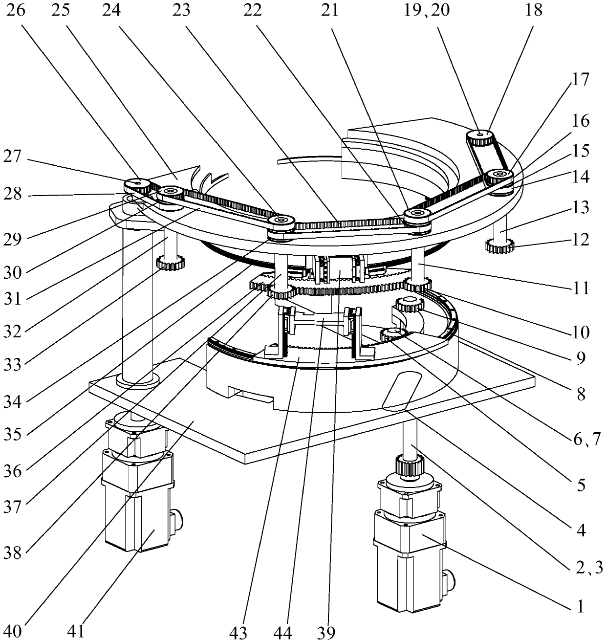
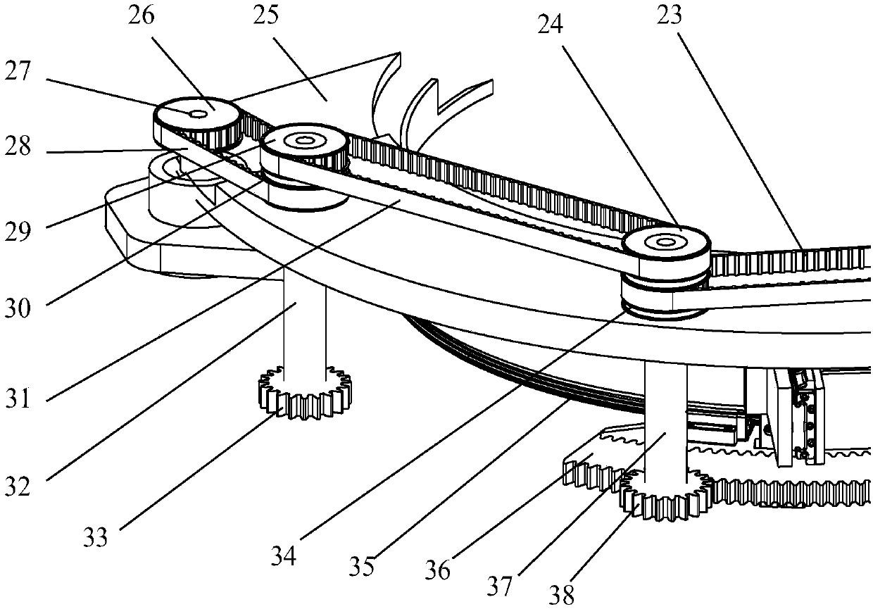
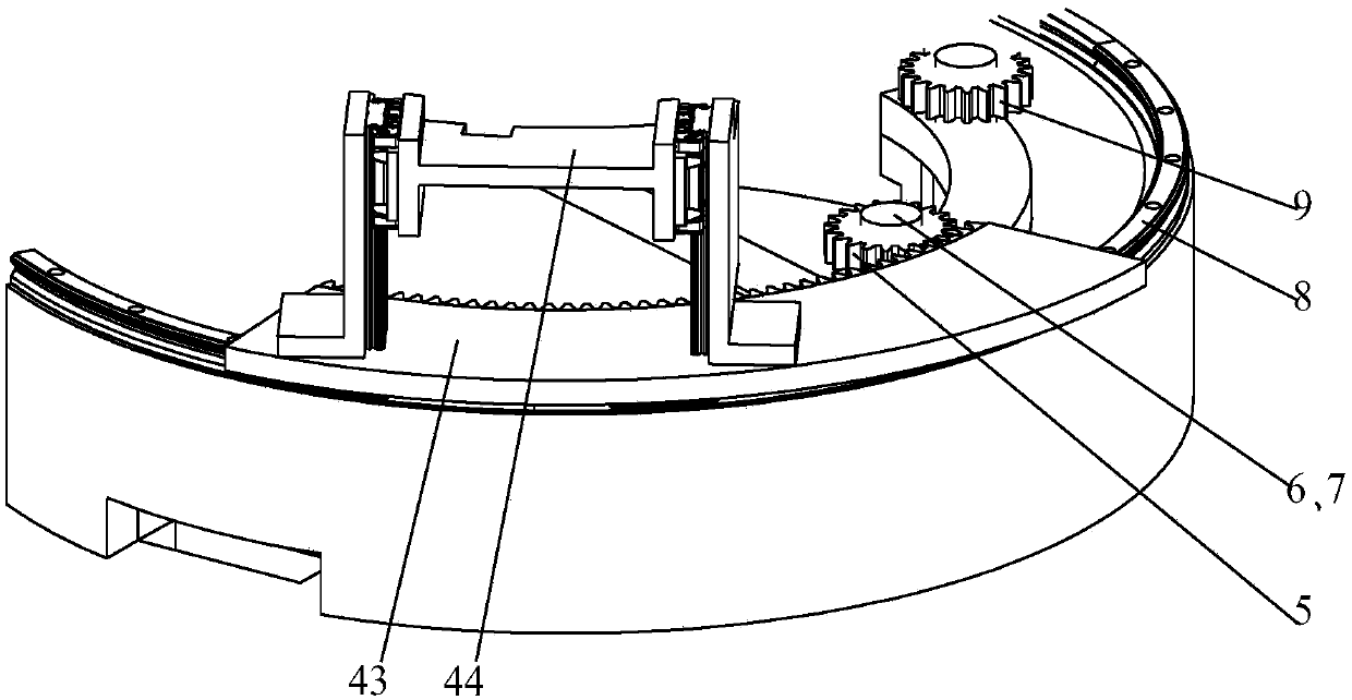
[0014] Such as Figure 1 ~ Figure 4 As shown, this embodiment relates to a clamping device that can be cross-wound, including: motor two 1, main shaft two 2, pulley twelve 3, toothed belt six 4, gear seven 5, shaft six 6, belt Wheel eleven 7, arc-shaped guide rail two 8, gear six 9, gear three 10, axis three 11, gear four 12, axis four 13, toothed belt four 14, belt wheel nine 15, toothed belt five 16, belt Wheel 8 17, belt wheel 10 18, shaft 5 19, gear 5 20, belt wheel 7 21, belt wheel 6 22, toothed belt 3 23, belt wheel 4 24, upper frame 25, belt wheel 1 26, spindle 1 27. Toothed belt one 28, belt wheel three 29, belt wheel two 30, toothe...


PUM


Abstract

The invention provides a clamping device capable of realizing cross surrounding. A belt pulley I and a belt pulley II are in transmission connection through a cog belt I; a belt pulley III and a belt pulley IV are in transmission connection through a cog belt II; a belt pulley V and a belt pulley VI are in transmission connection through a cog belt III; a belt pulley VII and a belt pulley VIII are in transmission connection through a cog belt V; a belt pulley IX and a belt pulley X are in transmission connection through a cog belt IV; a sector-shaped outer gear disk is glidingly connected with an arc-shaped guide rail I and is meshed with a gear I, a gear II, a gear III, a gear IV and a gear V; an upper clamp body is fixedly connected onto the sector-shaped outer gear disk; a spindle II and a shaft VI are mounted on a lower rack; a belt pulley XI and a gear VI are mounted on the spindle II; a belt pulley XII and a gear VII are mounted on the shaft VI; the belt pulley XI and the belt pulley XII are in transmission connection through a cog belt VI; an arc-shaped guide rail II is arranged on the lower rack; and a sector-shaped inner gear disk is glidingly connected with the arc-shaped guide rail II and is meshed with the gear VI and the gear VII.

Description

Technical field [0001] The invention relates to a clamping device that can be cross-circulated, and belongs to the technical field of clamping devices. Background technique [0002] The commonly used traveler cross-section shapes are hexagonal, U-shaped and square, etc., but the strength is not very high, and it cannot reach the necessary strength for some special-purpose tires. The traveler with a circular cross-section has high strength. It includes a ring-shaped traveler core and a winding steel wire spirally wound on the traveler core. The prior art adopts a rectangular or linear reciprocating winding action, which has frequent acceleration and deceleration, and the route Long, unoptimized trajectory, low speed, low efficiency, and processing accuracy is difficult to guarantee. Summary of the invention [0003] The purpose of the present invention is to solve the above-mentioned problems in the prior art, that is, the prior art adopts rectangular or linear reciprocating windi...

Claims


Application Information

Patent Timeline
Patent Type & Authority Patents(China)
IPC IPC(8): B21F37/00
CPCB21F37/00
Inventor 陈家轩于福利张庆春
Owner 哈尔滨工大宏图橡塑科技有限公司
Learn More