Circulation Dry Plate Cutting Equipment

A technology of cutting equipment and dry plates, which is applied in metal processing and other directions, can solve problems such as high replacement rate, influence of transmission accuracy, and plate size error, and achieve high dimensional consistency, improve repeatability, and ensure cutting accuracy.

Active Publication Date: 2018-08-10
李耀进
View PDF7 Cites 0 Cited by
  • Summary
  • Abstract
  • Description
  • Claims
  • Application Information

AI Technical Summary

Problems solved by technology

[0006] 1. The repeated cutting accuracy of the overall equipment is low. The cut boards are long and wide, and the diagonal size range is relatively random. Most of them are not within the specified error range. The overall cutting efficiency is low. Most products can only cut single sheets and cut more When stretching the boards, the upper and lower boards are often staggered. When the final cutting is performed, the same stack of boards will have different sizes.
[0007] 2. The applicability of common rails on the market is not strong: such as light rails and elevator rails, both of which require matching wheels to have a certain gap with them, so that the carrier will produce a certain amount of lateral movement or swing , the cut plate also has dimensional errors; if a more precise standard slider and slide rail combination are used, the dust on site will greatly affect it and the replacement rate will be high
[0008] 3. The harsh production environment on site has a certain impact on the transmission accuracy
[0009] 4. When the plate is cut, it is easy to cause chipping and corner drop on the cutting edge
[0011] 6. The idling time of the cutting motor is long, and the cutting motor does not perform the cutting action when the trolley returns with no load

Method used


Image

  • Circulation Dry Plate Cutting Equipment
  • Circulation Dry Plate Cutting Equipment
  • Circulation Dry Plate Cutting Equipment

Examples


Embodiment Construction

[0047] The following will clearly and completely describe the technical solutions in the embodiments of the present invention with reference to the accompanying drawings in the embodiments of the present invention. Obviously, the described embodiments are only some, not all, embodiments of the present invention. Based on the embodiments of the present invention, all other embodiments obtained by persons of ordinary skill in the art without creative efforts fall within the protection scope of the present invention.

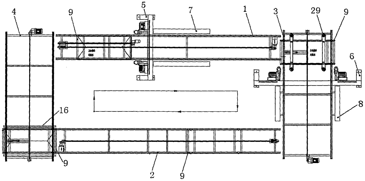
[0048] Such as figure 1 As shown, the circulation dry plate cutting equipment described in the embodiment of the present invention includes:

[0049] Two sets of cutting saw forward frame groups and two sets of cutting saw horizontal frame groups, the first cutting saw forward frame group 1, the second cutting saw forward frame group 2, the first cutting saw horizontal frame group 3 and the second cutting saw horizontal frame group 4 to form a rectangular running ...


PUM


Abstract

The invention relates to cyclic dry plate cutting equipment. According to the cyclic dry plate cutting equipment, a first cutting saw forward rack group, a second cutting saw forward rack group, a first cutting saw transversal rack group and a second cutting saw transversal rack group form a rectangular running mechanism; a transversal cutting saw group is vertically installed on the first cutting saw forward rack group, and a forward cutting saw group is vertically installed on the first cutting saw transversal rack group; automatic forward batten unloading mechanisms are installed at the two sides of the first cutting saw forward rack group, and automatic transversal batten unloading mechanisms are installed at the two sides of the first cutting saw transversal rack group; and four cyclic carrying running vehicles run among the stations of the rectangular running mechanism. The cyclic dry plate cutting equipment disclosed by the invention can be applied to a factory with a poor environment, the influence of dust on the equipment is low, a plurality of plates can be cut at the same time, the dimensions of the cut plates are basically the same and free from the phenomena of edge breakage, corner faults and the like, and plate cutting saws work all the time without an idle phenomenon.

Description

technical field [0001] The invention belongs to the field of building boards, in particular to circulating dry board cutting equipment. Background technique [0002] In the field of building boards, the cutting of dry boards has been plagued by the industry. At present, saws in the woodworking industry are mostly used for cutting. Because of the following differences between boards and wood in this industry: hard quality, easy to collapse edges, friction and scratches are not allowed on the surface, and the length of finished boards varies greatly. These qualitative differences determine that woodworking saws are not suitable for this industry. In actual operation, The cutting efficiency is low and the scrap rate is high. [0003] The equipment in the field of building panels is interlocking according to the process. The introduction of woodworking saws will affect the entire production process to a certain extent, causing the production process to be out of joint. [0004...

Claims


Application Information

Patent Timeline
Patent Type & Authority Patents(China)
IPC IPC(8): B26D1/01B26D7/26B26D7/06B26D7/18B26D7/01
Inventor 李耀进
Owner 李耀进
Why Eureka
Try Eureka