Cylindrical-component grinding device, and workpiece advancing apparatus and grinding method thereof

a technology of cylindrical components and grinding devices, which is applied in the direction of metal-working apparatus, manufacturing tools, lapping machines, etc., can solve the problems of slow improvement of excircle surface finishing precision (shape accuracy and dimensional consistency) of workpieces, reduce processing costs, and reduce the diameter difference of cylindrical rollers. , to achieve the effect of improving the shape accuracy and dimensional consistency of cylindrical surfaces, enhancing surface processing efficiencies of cylindrical components, and improving the accuracy of machining

Active Publication Date: 2017-09-28
TIANJIN UNIV
View PDF4 Cites 3 Cited by
  • Summary
  • Abstract
  • Description
  • Claims
  • Application Information

AI Technical Summary

Benefits of technology

[0008]Aiming at the problems in the prior art, a cylindrical-component grinding device and a grinding method using the same are provided in the present invention. The invention has the ability to meet demands of a mass production, to achieve a large removal of materials at a high position, and a small removal of that at a low position, and to realize a large material removal on the cylindrical surface of the cylindrical roller with a large diameter, and a small material removal on the cylindrical surface of the cylindrical roller with a small diameter, so as to improve the shape accuracy and dimensional consistency of cylindrical surfaces of the cylindrical roller, to enhance surface processing efficiencies of the cylindrical components (i.e. the cylindrical roller), and to reduce processing costs.

Problems solved by technology

However, due to the limitations of processing principles, the super-finishing method involves following technical defects.
In one aspect, variations of wear conditions of the whetstone and the super finishing roller are unfavorable for improving cylindrical surface size accuracy and shape accuracy of the cylindrical roller; in the other aspect, as in the through-feed centerless super-finishing method, only a limited number of cylindrical rollers are processed at the same time, and material removal amounts therein are almost independent of the difference between diameter thereof with that of the other cylindrical rollers of the same batch, so the through-feed centerless super-finishing method cannot obviously reduce the diameter difference of the cylindrical rollers.
The above two aspects may lead to a slow improvement on excircle surface finishing precisions (shape accuracy and dimensional consistency) of the workpiece, a long processing cycle, and a high cost.
During a grinding process, the retainer performs a revolution around a center of the grinding disc as well as a self rotation, under the effect of the upper and lower discs as well as the retainer, while the cylindrical roller performs a revolution around a center of the retainer and at the same time a rotation around an axis itself, thus involving a complicated spatial motion.
However, the double-disc grinding machine can only be used for excircle super-finishing on small batch (dozens to hundreds) of cylindrical workpiece.
For the large volume of bearing roller demand, it is difficult for the double-disc planetary grinding method to meet.
It can be seen that there is an inherent lack of processing precision when the excircle surface of the cylindrical workpiece is processed by the through-feed centerless super-finishing method, while the double-disc grinding method cannot meet the demand of a mass production, and thus there is an urgent need for a super-finishing device for excircle surface of the cylindrical component, which may achieve a high processing precision and a mass production, so as to meet requirements of the high precision cylindrical roller bearing on the processing precision of excircle surfaces of the cylindrical rollers, as well as the demand of production scales.

Method used


Image

  • Cylindrical-component grinding device, and workpiece advancing apparatus and grinding method thereof
  • Cylindrical-component grinding device, and workpiece advancing apparatus and grinding method thereof
  • Cylindrical-component grinding device, and workpiece advancing apparatus and grinding method thereof

Examples


Embodiment Construction

[0047]The technical solution of the present invention will now be described in further detail with reference to the accompanying drawings and specific examples.

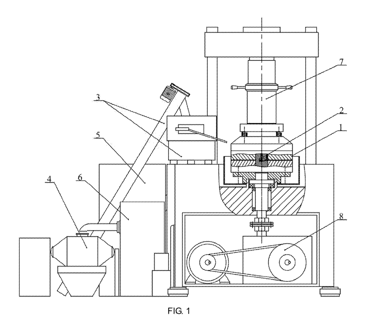
[0048]As shown in FIG. 1, a cylindrical-component grinding device proposed in the present invention includes a loading apparatus 7, a power system 8, and a workpiece advancing apparatus 2, a grinding disc apparatus 1, a workpiece and grinding fluid separating apparatus 5, a workpiece cleaning apparatus 6 and workpiece mixing apparatus 4, the later five apparatuses connecting with a workpiece conveying apparatus 3 in sequence. The loading apparatus 7 is configured for material loading of the grinding disc apparatus 1 and the power system 8 is configured for driving the grinding disc apparatus 1.

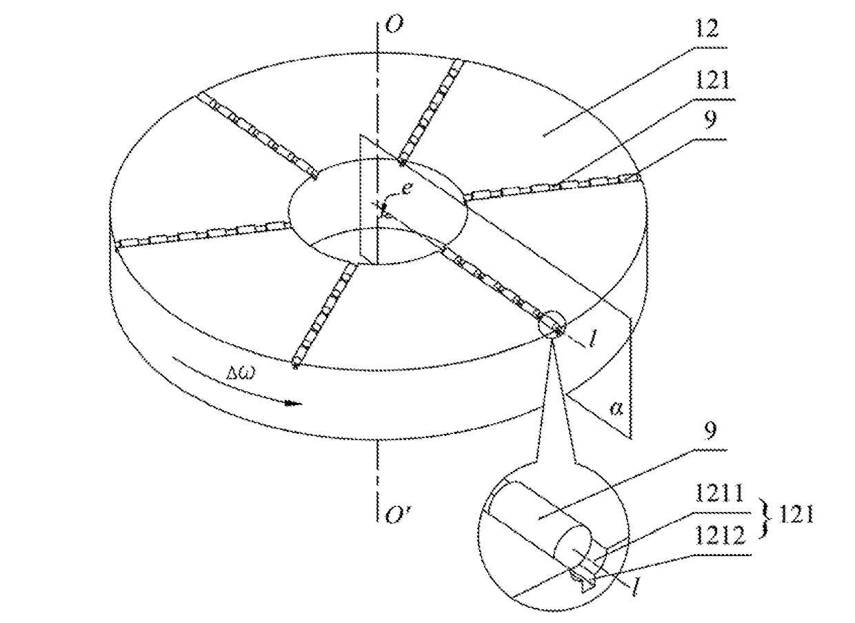
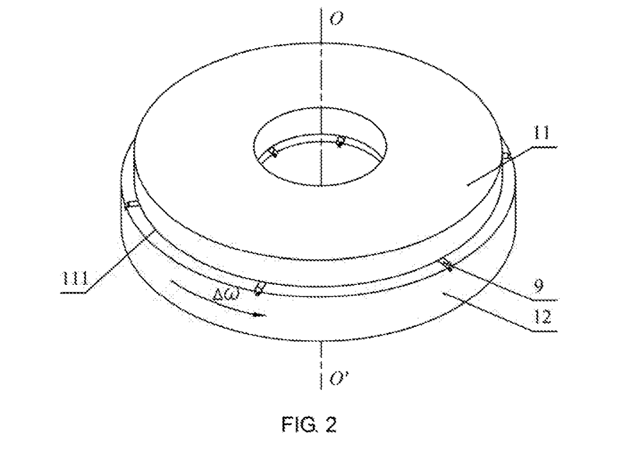
[0049]As shown in FIG. 2, the grinding disc apparatus 1 includes a first grinding disc 11 and a second grinding disc 12, and the second grinding disc 12 and the first grinding disc 11 rotate relative to each other. The second grinding d...


PUM


Abstract

A double-disc straight groove cylindrical-component surface grinding disc, includes a first grinding disc and a second grinding disc, rotating relative to each other; the the first grinding disc's working face is planar; the second grinding disc's surface, opposite the first grinding disc, includes a set of radial straight grooves, with groove faces of the straight grooves are the working face of the second grinding disc; the cross-sectional outline of the working face of the second grinding disc is arcuate or V-shaped or is a V-shape having an arc; during grinding, a workpiece spins inside the straight grooves, while under the effect of an advancing apparatus, the workpiece slides in translational motion along the straight grooves. The described grinding disc device has high-volume production capabilities, and the shape accuracy and size consistency of the cylindrical roller's cylindrical surface and the efficiency in machining are improved, and machining cost is reduced.

Description

CROSS-REFERENCE TO RELATED APPLICATIONS[0001]This application is a continuation of International Patent Application No. PCT / CN2015 / 095395 with a filing date of Nov. 24, 2015, designating the United States, now pending, and further claims priority to Chinese Patent. Application No. 201410784413.3 with a filing date of Dec. 16, 2014. The content of the aforementioned application, including any intervening amendments thereto, are incorporated herein by reference.TECHNICAL FIELD[0002]The present invention relates to a technical field of precision machining on excircle surfaces of high precision cylindrical components, and more particularly to an excircle surface grinding device for a cylindrical-component and a method thereof.BACKGROUND OF THE PRESENT INVENTION[0003]Cylindrical roller bearings are widely used in various types of rotating machines. As a cylindrical roller is an important component of the cylindrical roller bearing, excircle surfaces machining precision of the cylindrical...

Claims


Application Information

Patent Timeline
Patent Type & Authority Applications(United States)
IPC IPC(8): B24B37/02B24B37/34
CPCB24B37/022B24B37/345B24B37/16B24B37/04B24B37/26B24B37/02B24B37/025B24B37/08
Inventor REN, CHENGZUDENG, XIAOFANHE, YINGLUNCHEN, GUANGJIN, XINMIN
Owner TIANJIN UNIV
Why Eureka
Try Eureka