a drinking bucket

A drinking water bucket and water dispenser technology, which is applied in the directions of packaging, closing, transportation and packaging, can solve the problems of inconvenience, unenvironmental protection, and inability to reseal the drinking water bucket, and achieve the effect of convenient installation or disassembly

Active Publication Date: 2019-01-18
凯米特新材料科技有限公司
View PDF11 Cites 0 Cited by
  • Summary
  • Abstract
  • Description
  • Claims
  • Application Information

AI Technical Summary

Problems solved by technology

Most of the existing drinking water buckets are cylindrical. Because of a bucket of drinking water, when the water delivery man carries the drinking water bucket, he has nowhere to grab it, which is often very inconvenient. It is also very laborious to replace the drinking water bucket on the water dispenser.
[0003] Existing drinking water buckets include a bucket body and a bucket head. The bucket head is connected to the upper end of the bucket body. There is an opening on the bucket head. The opening is generally sealed with a sticker to directly close the outlet of the bucket head. A hard cover is used on the inner wall of the opening, and there is a curved dent on the hard cover; when installing the drinking water bucket on the water dispenser, first remove the sticker on the head of the bucket, and then tilt the bucket body to use Lift the drinking water bucket with both hands, and make the drinking water bucket form an upside-down shape, and then insert the bucket head into the water inlet connector of the water dispenser, because the hard cover and adhesive stickers are disposable and will be destroyed once opened , can't reseal the drinking water bucket, can't prevent pollution very well, and it's not green
[0004] There is only one hard cover on the head of the bucket, which seals the drinking water of the whole bottled water. As long as the dent on the hard cover breaks, the drinking water will flow out of the drinking water bucket. After entering the water dispenser, because the water overflows from the opening of the bucket head, it cannot directly enter the water dispenser, so it is easily polluted by the outside world.

Method used


Image

  • a drinking bucket
  • a drinking bucket
  • a drinking bucket

Examples


Embodiment Construction

[0012] The present invention is described in further detail below by embodiment, and embodiment is only used for illustrating the present invention, does not limit the scope of the present invention.

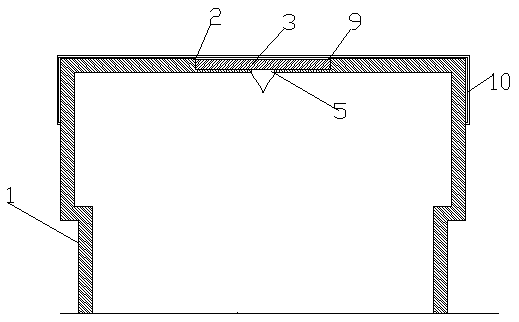
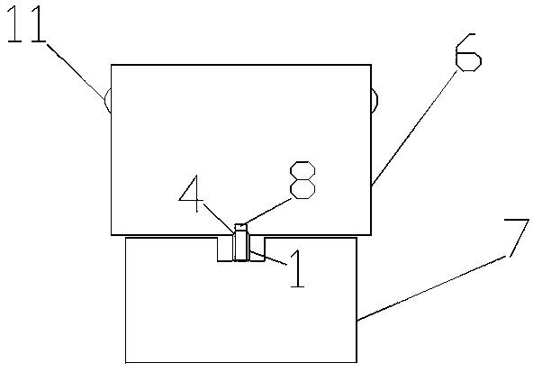
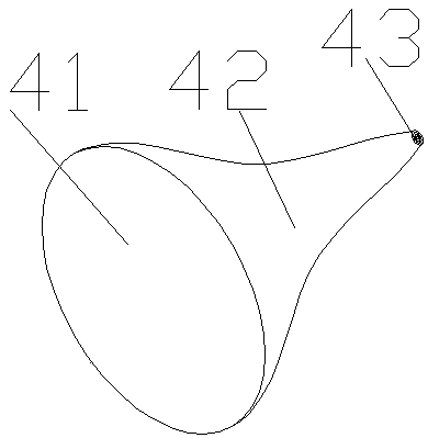
[0013] Such as figure 1 , 2 A kind of drinking water barrel shown in , 3, 4, comprises barrel body 6 and barrel head 1, and barrel head 1 is fixedly connected on the upper end of barrel body 6, and water outlet 5 is set on the barrel head 1, and the upper end of described water outlet 5 is set There is a groove 2, and the groove 2 is arranged in the middle of the upper end face of the barrel head 1. The diameter of the groove 2 can be adjusted according to the actual situation. The water inlet joint 8 is matched and set, the groove 2 is connected to the cover 3 by screw fixing, the cover 3 is provided with a rotating shaft 9, the rotating shaft 9 is a columnar protrusion, and the lower end of the water outlet 5 is fixed to the upper end of the hollow elastic rubber sleeve The ...


PUM


Abstract

The invention particularly relates to a drinking bucket. The drinking bucket comprises a bucket body and a bucket head. The bucket head is fixedly connected to the upper end of the bucket body. A water outlet is formed in the bucket head. A groove is formed in the upper end of the water outlet. A sealing cover is connected in the groove in a threaded fixing manner. The lower end of the water outlet and the upper end of a hollow elastic rubber sleeve are fixedly connected. According to the drinking bucket, the sealing cover is connected in the groove in the threaded manner, and a rotating shaft is arranged, so that mounting or dismounting of the sealing cover is convenient; and after a water inlet connector of a water dispenser enters the hollow elastic rubber sleeve, the tail end of the hollow elastic rubber sleeve wraps the water inlet connector of the water dispenser under the action of shrinkage force of elastic materials, then water can be sealed in the bucket body, sealing is convenient, and the water does not overflow out of the bucket body during using.

Description

technical field [0001] The invention relates to the field of drinking water accessories, in particular to a drinking water barrel. Background technique [0002] Many families and units use drinking water. Most of the existing drinking water buckets are cylindrical. Because of a bucket of drinking water, when the water delivery man carries the drinking water bucket, he has nowhere to grab it, which is often very inconvenient. It is also very laborious to change the drinking water bucket on the water dispenser. [0003] Existing drinking water buckets include a bucket body and a bucket head. The bucket head is connected to the upper end of the bucket body. There is an opening on the bucket head. The opening is generally sealed with a sticker to directly close the outlet of the bucket head. A hard cover is used on the inner wall of the opening, and there is a curved dent on the hard cover; when installing the drinking water bucket on the water dispenser, first remove the stick...

Claims


Application Information

Patent Timeline
Patent Type & Authority Patents(China)
IPC IPC(8): B65D47/08B65D51/18
CPCB65D47/0866B65D51/18B65D2251/0015
Inventor 孙冠州
Owner 凯米特新材料科技有限公司
Why Eureka
Try Eureka