
Power grid dispatching control device

A control device and power grid dispatching technology, applied in electrical components, supervision desk/panel, etc., to achieve good control effect and less energy consumption

Active Publication Date: 2017-02-08
国网黑龙江省电力有限公司大兴安岭供电公司 +1
View PDF4 Cites 0 Cited by
  • Summary
  • Abstract
  • Description
  • Claims
  • Application Information

AI Technical Summary

Problems solved by technology

[0003] The purpose of the present invention is to solve the problem that the existing power grid dispatching control device must display through an external display, and proposes a power grid dispatching control device

Method used


Image

  • Power grid dispatching control device
  • Power grid dispatching control device

Examples


specific Embodiment approach 1

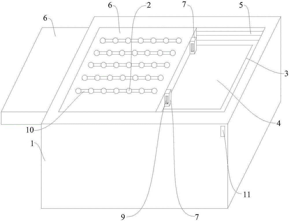
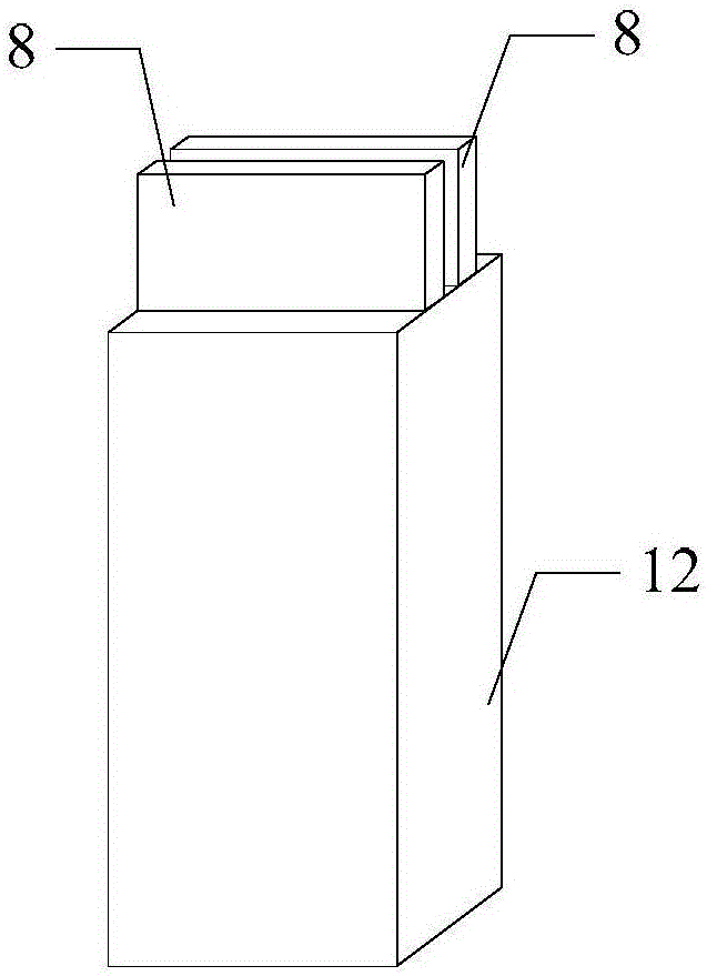
[0028] Specific implementation mode one: combine figure 1 Describe this embodiment, a power grid dispatching control device described in this embodiment, including a control cabinet 1, a manual control panel 4, a sliding cover 6, a limit rod 12, an LED lamp group 2, and a plurality of contact switches;

[0029] The manual control panel 4 is arranged inside the control cabinet 1, and the manual control panel 4 is used to schedule the operation state of the power grid;

[0030] The sliding cover plate 6 is slidingly connected with the control cabinet 1, and one side of the sliding cover plate 6 is provided with a protrusion 7, and the protrusion 7 is provided with a card slot 9; the sliding cover plate 6 is used to cover the opening side of the control cabinet 1, When not operating the hand control panel 4, ensure that the hand control panel 4 is in a closed space to prevent dust from falling into the hand control panel 4 and affect the service life of the hand control panel 4; ...

specific Embodiment approach 2

[0036] Specific embodiment 2: This embodiment is to further limit the power grid dispatching control device described in specific embodiment 1. In this embodiment, the side wall of the control cabinet 1 close to the opening side of the control cabinet 1 is provided with Control grooves, wherein the control groove on one side wall is a transparent groove, the control groove opposite to the transparent groove is a fixed groove 3, and the control grooves on the other two opposite side walls are guide grooves 5;

[0037] The sliding cover plate 6 passes through the through groove and is arranged on the guide groove 5;

[0038] One end of the hand control panel 4 is arranged on the fixing groove 3, and the fixing groove 3 is used to fix the hand control panel 4, and it is convenient to find faults and to repair and repair the hand control panel 4 when the hand control panel 4 breaks down. replace.

specific Embodiment approach 3

[0039] Embodiment 3: This embodiment further limits the power grid dispatching control device described in Embodiment 2. In this embodiment, the side wall of the control cabinet 1 provided with the fixing groove 3 is provided with a connecting groove; The connecting groove is used to accommodate the protrusion 7 on the sliding cover plate 6;

[0040] The limiting groove 11 communicates with the connecting groove.

[0041] In this embodiment, when the sliding cover plate 6 covers the control cabinet 1 by opening the connecting groove, the sealing effect is better, and the service life of the hand control panel 4 can be increased.


PUM


Abstract

The invention provides a power grid dispatching control device which relates to power grid control power equipment. The power grid dispatching control device aims to settle a problem of a requirement for an external display device for displaying in an existing power grid dispatching control device. According to the power grid dispatching control device, a sliding cover plate is slidably connected with a control cabinet; one side of the sliding cover plate is provided projections, and the projections are provided with snapping troughs; the sidewall of the power grid dispatching control device is provided with a spacing trough; a spacing rod is arranged in the spacing trough; the spacing rod is slidably connected with the spacing trough; a snap block is fixed on the spacing rod; an LED lamp set and contact switches are arranged on the external surface of the sliding cover plate; the signal output end of each contact switch is connected with the signal input end of a switch on a manual control panel; the signal output end of the manual control panel is fixed to one end of the spacing rod; and the signal input end of the LED lamp set is arranged on the snapping trough of the boss. The power grid dispatching control device is advantageous in that the LED lamp set is used for performing real-time simulation on the dispatching state of the whole power grid so that more direct displaying of the control cabinet is realized; and the contact switches are used for controlling the manual control panel, thereby realizing higher convenience in use and lower energy consumption.

Description

technical field [0001] The invention relates to a grid control power equipment. Background technique [0002] The command center of the power grid assumes the main responsibility for the safe operation of the entire power grid. Power grid dispatching is an effective management method adopted to ensure the safe and stable operation of the power grid, reliable external power supply, and orderly progress of various power production tasks. With today's rapid development, more and more old control devices can no longer meet the needs of today's power grid management. The existing power grid dispatching automation control devices have a very simple structure and single function, and must be displayed through an external display. Contents of the invention [0003] The purpose of the present invention is to solve the problem that the existing power grid dispatching control device must display through an external display, and propose a power grid dispatching control device. [000...

Claims


Application Information

Patent Timeline
Patent Type & Authority Applications(China)
IPC IPC(8): H02B15/00
CPCH02B15/00
Inventor 金忠达王野藤王言军王学军刘晓磊王馗朱劲军杨兆华杨滨白锋
Owner 国网黑龙江省电力有限公司大兴安岭供电公司
Learn More