Pin shaft feeder

A feeder and pin shaft technology, applied in the direction of metal chains, etc., can solve problems such as low efficiency and high labor costs, and achieve the effects of improving production efficiency, saving manpower, and simple operation

Active Publication Date: 2017-02-15
SUZHOU SHUNGE INTELLIGENT TECH
View PDF5 Cites 10 Cited by
  • Summary
  • Abstract
  • Description
  • Claims
  • Application Information

AI Technical Summary

Problems solved by technology

[0002] Roller chains have been used in all aspects of our life. In one of its production processes, the pin shaft needs to be inserted into the connecting piece to fix the chain piece and the chain piece together to form a chain. In the current production, it is often used Assembly is done manually, which has the disadvantages of low efficiency and high labor costs

Method used


Image

  • Pin shaft feeder
  • Pin shaft feeder

Examples


Embodiment Construction

[0020] In order to make the object, technical solution and advantages of the present invention clearer, the present invention will be further described in detail below in conjunction with the accompanying drawings and embodiments. It should be understood that the specific embodiments described here are only used to explain the present invention, not to limit the present invention.

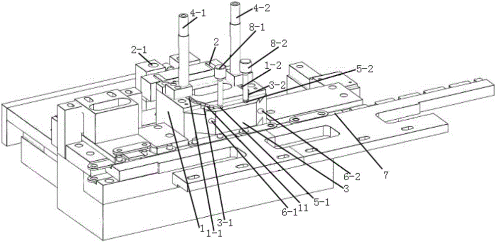
[0021] Such as figure 1 As shown, a pin feeding machine includes: a pin feeding main body 1, and two grooves are respectively arranged on both sides of the pin feeding main body 1, that is, a first groove 1-1 and a second groove 1- 2; wherein the first groove 1-1 and the second groove 1-2 can be used for storing and conducting the pin shaft 9 .

[0022] Behind the first groove 1-1 and the second groove 1-2, there is a pin push plate 2 that can move back and forth under the drive of the cylinder 2-1, and the pin push plate 2 can push the pin 9 to the first The first track 3-1 and the second track ...


PUM


Abstract

The invention provides a pin shaft feeder. The pin shaft feeder comprises a pin shaft feeding body and a pin shaft discharging mold. Two grooves are formed in the two sides of the pin shaft feeding body correspondingly. A pin shaft push plate is arranged behind each groove, and each pin shaft push plate can be driven by an air cylinder to do reciprocating motion. The pin shaft discharging mold is in the shape of a trapezoid. Two rails which are each connected with the corresponding groove are arranged on the edges of the two oblique sides of the trapezoid correspondingly. A pin shaft discharging pipe is arranged at the end, adjacent to the corresponding pin shaft push plate, of each groove. A vertical through hole is formed in the other end of each rail. Full-automatic production can be achieved, operation is easy and convenient, a large amount of manpower is saved, and the production efficiency is also improved.

Description

technical field [0001] The invention relates to the field of feeders, in particular to a pin feeder. Background technique [0002] Roller chains have been used in all aspects of our life. In one of its production processes, the pin shaft needs to be inserted into the connecting piece to fix the chain piece and the chain piece together to form a chain. In the current production, it is often used Assembly is performed manually, which has the disadvantages of low efficiency and high labor costs. Contents of the invention [0003] In view of this, the present invention provides a pin feeder, which can not only be operated easily and conveniently, but also can save cost and improve efficiency. [0004] To achieve the above object, the present invention adopts the following technical solutions: [0005] A pin feeder, the pin feeder includes: [0006] The pin shaft feeding main body, two grooves are respectively arranged on both sides of the pin shaft feeding main body; a pin ...

Claims


Application Information

Patent Timeline
Patent Type & Authority Applications(China)
IPC IPC(8): B21L9/06
CPCB21L9/06
Inventor 何治富
Owner SUZHOU SHUNGE INTELLIGENT TECH
Why Eureka
Try Eureka