Ejection device for bumper mould

A technology of ejecting device and bumper, which is applied to household appliances, other household appliances, applications, etc., can solve the problems of complex mold, reduce mold release efficiency, increase mold release cost, etc., achieve simple and compact structure, and improve mold release efficiency. Effect

Active Publication Date: 2017-02-15
NINGBO FANGZHENG TOOL
View PDF7 Cites 9 Cited by
  • Summary
  • Abstract
  • Description
  • Claims
  • Application Information

AI Technical Summary

Problems solved by technology

[0003] Generally, the demoulding requirements of automobile bumper products can be basically achieved by using the existing mold structure, but in actual production, especially when the above-mentioned structural requirements for connecting the panels at the position of the lampshade of the headlight or rear light are added, use Traditional molds cannot realize the one-time complete demoulding of automobile bumper products. This is because the panel at the position of the lampshade has an inner concave surface, so it is necessary to set a small straight top structure in the mold at the panel of the lampshade. There are large straight top structure, small straight top structure and inclined top structure at the position of the bar lampshade. Therefore, the inside of the mold at this position is very complicated. At the same time, due to the existence of the inclined top structure, the large straight top structure, small straight top structure The demoulding of the inclined roof struc

Method used


Image

  • Ejection device for bumper mould
  • Ejection device for bumper mould
  • Ejection device for bumper mould

Examples


Embodiment Construction

[0023] The present invention will be described in further detail below in conjunction with the accompanying drawings and specific embodiments.

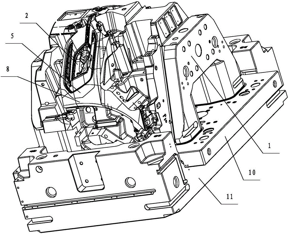
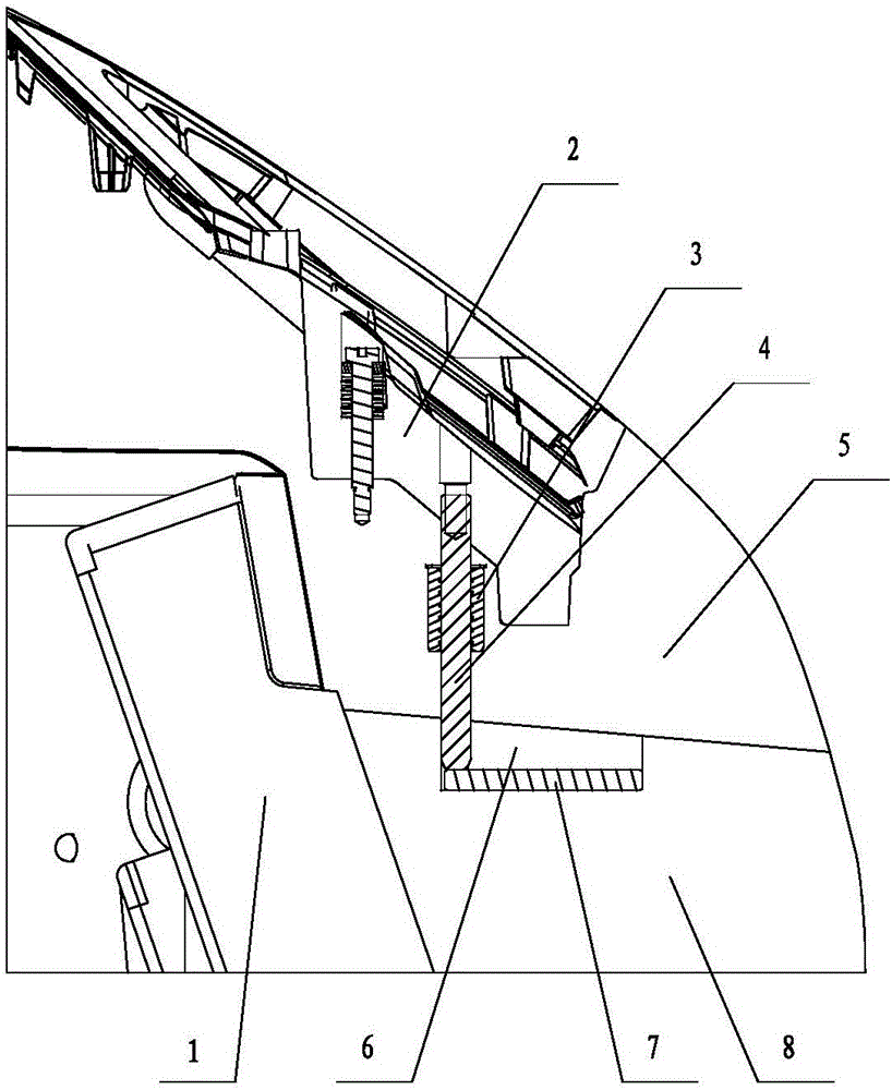
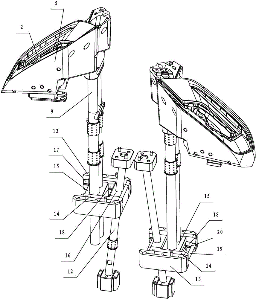
[0024] Depend on Figure 1 to Figure 8 Shown the present invention is used for the structural representation of the bumper mould's ejection device as can be known, and it comprises the small straight ejection mechanism that is used at automobile bumper lampshade panel place, big straight ejection mechanism, inclined ejection mechanism and with small straight ejection mechanism, The movable die inserting core 1 that both the large straight top mechanism and the inclined top mechanism are connected. The small straight top block 2 in the described small straight top mechanism is embedded in the large straight top block 5 in the large straight top mechanism, the inclined top block 8 in the inclined top mechanism and the large straight top block in the large straight top mechanism 5 Swipe to connect. The lower end of the large straight t...


PUM


Abstract

The invention discloses an ejection device for a bumper mould. The ejection device for the bumper mould comprises a small straight ejection mechanism, a big straight ejection mechanism, an inclined ejection mechanism and a movable mould insert core (1). Small straight ejection blocks (2) are embedded in big straight ejection blocks (5); inclined ejection blocks (8) are slidably connected with the big straight ejection blocks (5); the lower ends of big straight ejection guide rods (9) are slidably connected into the movable mould insert core (1) through sliding foot components; inclined ejection guide rods (12) are slidably connected with the sliding foot components; small straight ejection guide rods (4) and the big straight ejection blocks (5) are slidably connected in a vertical direction; the lower ends of the small straight ejection guide rods (4) and the big straight ejection blocks (5) are slidably connected with the inclined ejection blocks (8) in a horizontal direction; and return stroke structures for automatically separating the small straight ejection blocks (2) and the big straight ejection blocks (5) are arranged in the sliding components. By adopting the structure, the ejection device for the bumper mould is simple and compact in structure, and can accurately realize each demoulding action without damaging a product.

Description

technical field [0001] The invention relates to the technical field of moulds, in particular to an ejector for bumper moulds. Background technique [0002] With the development of the automobile industry, the automobile bumper, as an important safety device, in addition to its protective function, also pursues light weight. In order to achieve the purpose of light weight, the front and rear bumpers of the automobile are made of plastic materials through the mold. Injection molded. The car bumper made of plastic has good strength, rigidity and decoration, and can play a buffer role when the car collides, protecting the front and rear car bodies. In the prior art, the automobile bumper will connect the panels at the position of the lampshade of the headlight or the rear light as a whole to increase the aesthetics, but in this way, the complexity of the automobile bumper is increased, and the inner surface has a curved surface , Undercut and other structures, which bring grea...

Claims


Application Information

Patent Timeline
IPC IPC(8): B29C45/40B29L31/30
CPCB29C45/4005B29C45/401B29L2031/3044
Inventor 刘扬叶军胡迪金伟王一栋应可国
Owner NINGBO FANGZHENG TOOL
Why Eureka
Try Eureka