Braking control method for a peak-pushing locomotive in hump shunting mode

A technology for brake control and locomotives, which is applied to the control system of the transportation center, railway car body components, railway signals and safety, etc. It can solve the problems of high wiring difficulty, adverse effects on the reliability of the brakes, and trouble.

Active Publication Date: 2018-06-22
QINGDAO SRI TECH CO LTD
View PDF5 Cites 0 Cited by
  • Summary
  • Abstract
  • Description
  • Claims
  • Application Information

AI Technical Summary

Problems solved by technology

However, this method needs to add an additional braking junction box on the locomotive brake to receive instructions. For the highly complex and sophisticated wiring system of the locomotive braking system, this kind of modification is troublesome to implement, and requires the electrical interface of the brake Re-wiring, the wiring is difficult, and it also has an adverse effect on the reliability of the brake

Method used


Image

  • Braking control method for a peak-pushing locomotive in hump shunting mode
  • Braking control method for a peak-pushing locomotive in hump shunting mode

Examples


Embodiment Construction

[0027] The following will clearly and completely describe the technical solutions in the embodiments of the present invention with reference to the accompanying drawings in the embodiments of the present invention. Obviously, the described embodiments are only some, not all, embodiments of the present invention. Based on the embodiments of the present invention, all other embodiments obtained by persons of ordinary skill in the art without making creative efforts belong to the protection scope of the present invention.

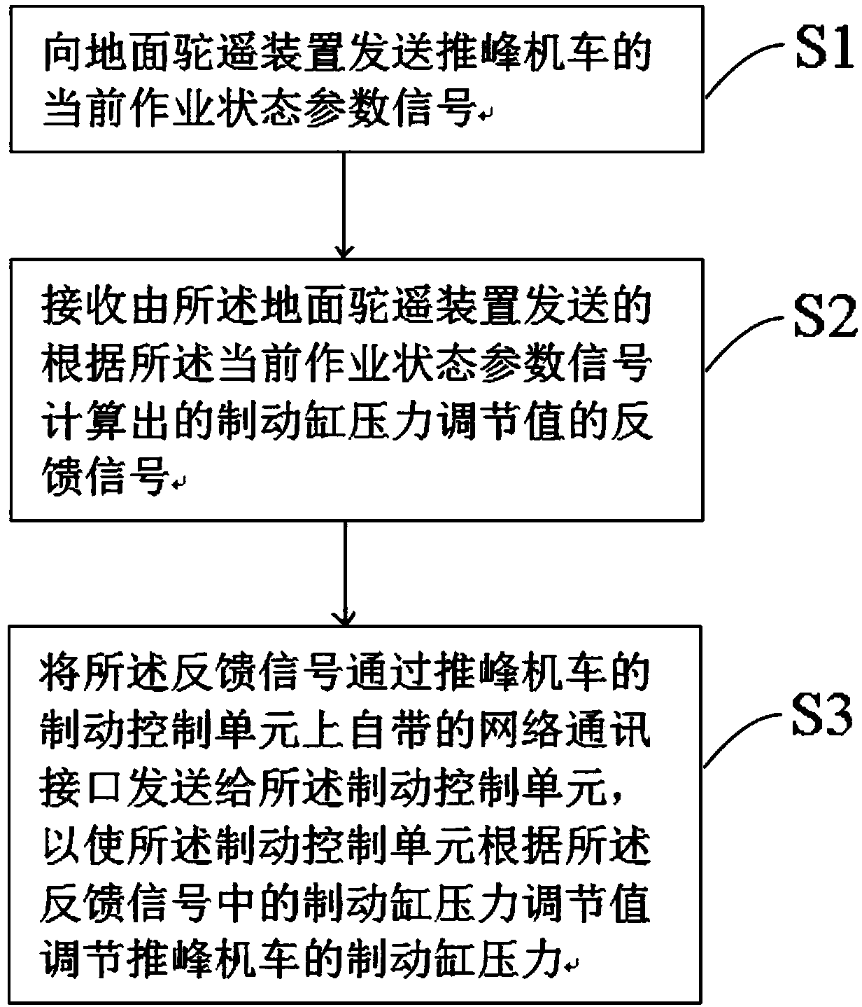
[0028] Please refer to figure 1 , figure 1 It is a flowchart of a locomotive brake operation and maintenance method in a specific embodiment provided by the present invention.

[0029] In a specific embodiment provided by the present invention, the braking control method of the peak-pushing locomotive in the hump shunting mode mainly includes three steps, which are: sending the current operating state parameters of the peak-pushing locomotive to the ground hu...


PUM


Abstract

The invention discloses a braking control method for a peak-pushing locomotive under the hump shunting mode, comprising: sending the current operating state parameter signal of the peak-pushing locomotive to the ground camel remote device; The feedback signal of the brake cylinder pressure adjustment value calculated by the parameter signal; the feedback signal is sent to the brake control unit through the network communication interface on the brake control unit of the peak-pushing locomotive, so that the brake control unit can The brake cylinder pressure adjustment value in adjusts the brake cylinder pressure of the peak pushing locomotive. The present invention utilizes the original hardware circuit system of the peak-pushing locomotive to complete the sending and receiving of feedback signals, without additionally adding a dedicated transceiver device, avoiding modification of the hardware circuit system of the peak-pushing locomotive, and realizing the peak-pushing locomotive on the hump at low cost. Brake control in shunting mode. The invention also discloses a brake control system for a peak-pushing locomotive in a hump shunting mode, and its beneficial effect is as above.

Description

technical field [0001] The invention relates to the technical field of locomotive braking and communication, in particular to a braking control method for a peak pushing locomotive in a hump shunting mode. Background technique [0002] Hump ​​shunting is to raise a part of the railway roadbed to a certain height at the marshalling station, forming a hump-like height difference with the conventional roadbed and designing it into a suitable slope. Using the potential energy generated by the gravity and height difference of the vehicle, the marshalling will be required. The vehicle is pushed to the top of the hump by a locomotive, that is, the hump is pushed, and the vehicle is unhooked on the hump, that is, the hump is disintegrated, and the train is slid down to the bottom of the hump to reach the marshalling yard. The locomotive used for pushing in this process can be called peak pushing locomotive, and the hump pushing operation is also called peak pushing operation. [00...

Claims


Application Information

Patent Timeline
Patent Type & Authority Patents(China)
IPC IPC(8): B61L27/00
CPCB61L27/70B61L27/20
Inventor 罗智迅刘杰艾正武乐燕飞王龙泉
Owner QINGDAO SRI TECH CO LTD
Why Eureka
Try Eureka