
Vibration disc discharge, cutting and separation device

A vibrating plate and discharge cylinder technology, applied in the field of mechanical equipment, can solve the problems of reducing work efficiency and increasing the difficulty of material distribution, and achieves the effect of simple structure, fast movement speed and compact design

Inactive Publication Date: 2017-02-15
WUXI CHUANGHENG MACHINERY
View PDF9 Cites 0 Cited by
  • Summary
  • Abstract
  • Description
  • Claims
  • Application Information

AI Technical Summary

Problems solved by technology

[0002] With the rapid development of industrial production, small fasteners such as screws are used in various mechanical parts. Small fasteners such as screws require multiple processes in the preparation process, and material distribution is an important process in production. The traditional parting adopts manual parting by the operator or picking up single parts. When the size of the fastener is smaller, the difficulty of parting is increased and the work efficiency is reduced.

Method used


Image

  • Vibration disc discharge, cutting and separation device
  • Vibration disc discharge, cutting and separation device

Examples


Embodiment Construction

[0011] The present invention will be further described below in conjunction with the accompanying drawings.

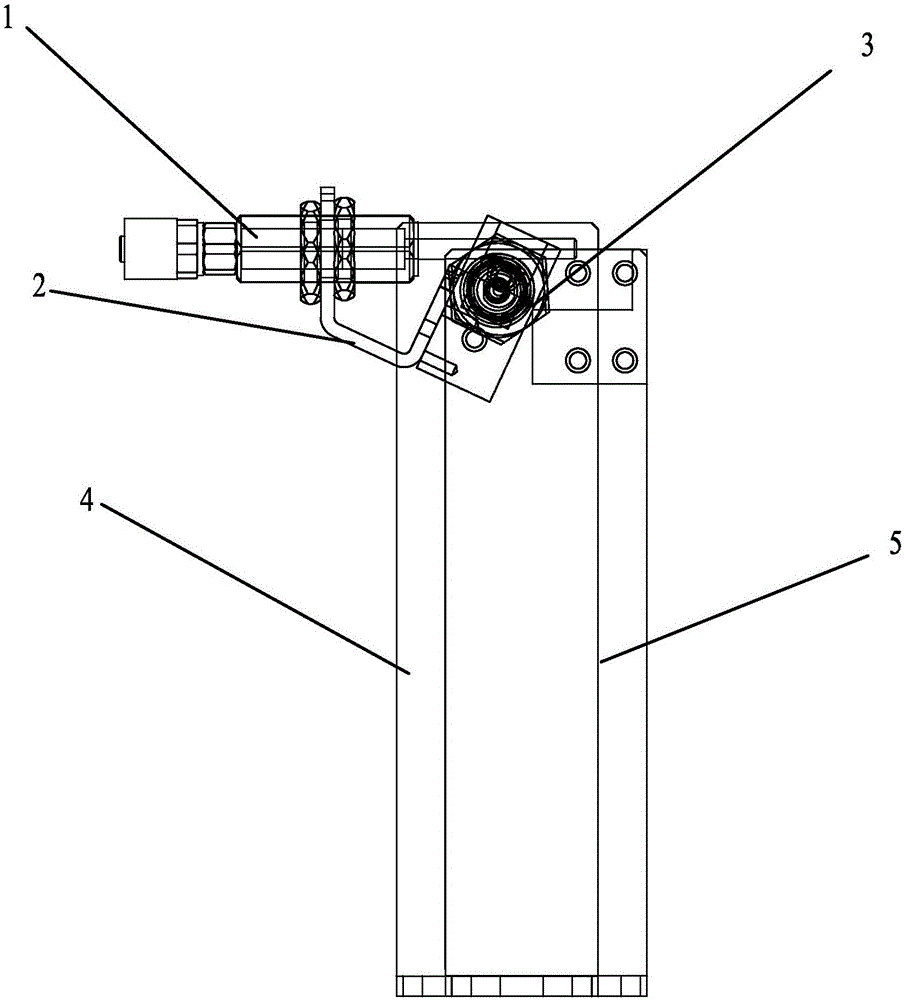
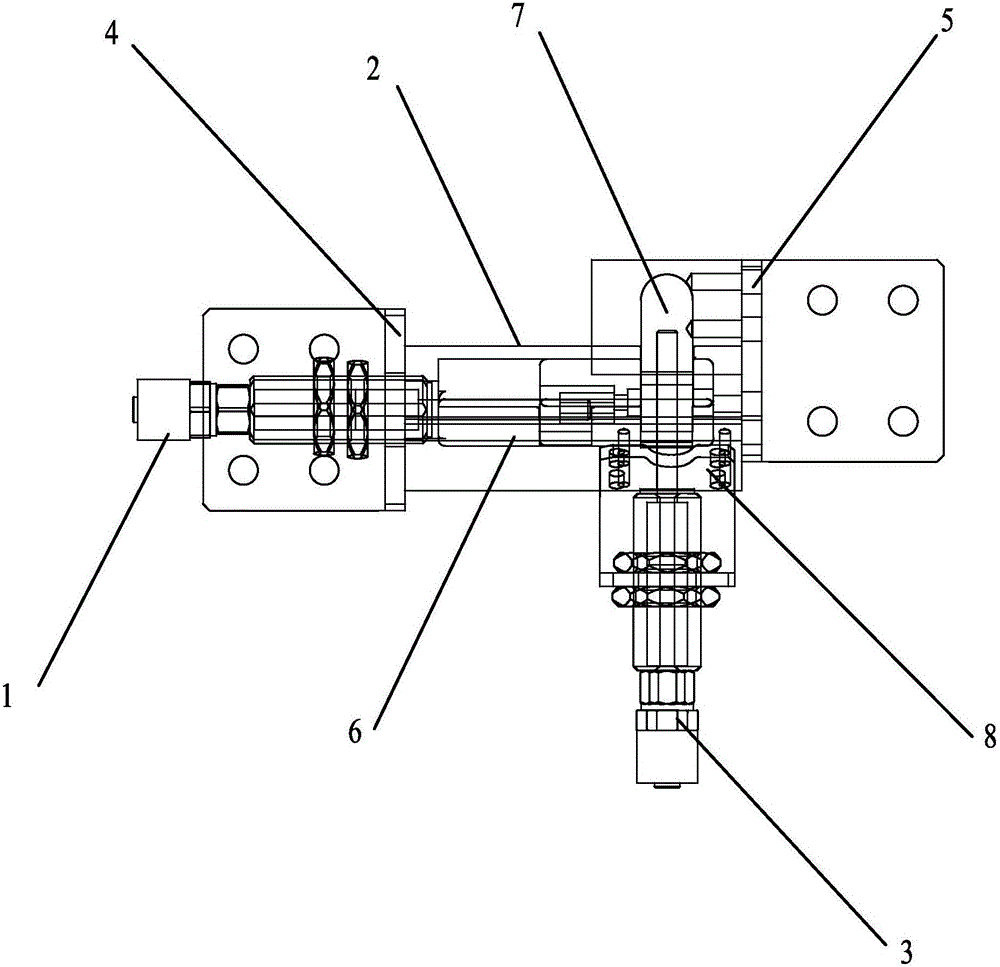
[0012] Such as Figure 1-Figure 2 As shown, a vibrating disc cutting and dividing device includes a feeding cylinder 1, a chute fixing block 2, a discharging cylinder 3, a first bracket 4 and a second bracket 5; the first bracket 4 and the second bracket 5 are in the form of L-shaped, the first bracket 4 and the second bracket 5 are arranged in parallel, the feed cylinder 1 is set on one side of the first bracket 4, and the chute fixing block 2 is arranged between the first bracket 4 and the second bracket 5, and the chute is fixed A hollow feeding cavity 6 is set in the middle of the block 2, and a connecting piece 8 is set on one side of the chute fixing block 2, and a discharging cylinder 3 is fixedly connected to the connecting piece 8, and the discharging cylinder 3 is perpendicular to the feeding cylinder 1 Set, the other side of the chute fixed block 2 is provi...


PUM


Abstract

The invention relates to a vibration disc discharge, cutting and separation device. The vibration disc discharge, cutting and separation device comprises a feeding cylinder, a chute fixed block, a discharge cylinder, a first bracket and a second bracket; the first bracket and the second bracket are arranged in parallel; the feeding cylinder is arranged on one side of the first bracket; the chute fixed block is arranged between the first bracket and the second bracket; a hollow feeding cavity is formed in middle of the chute fixed block; a connecting piece is arranged on one side of the chute fixed block, and is fixedly connected with the discharge cylinder; the discharge cylinder is perpendicular to the feeding cylinder; and a discharge cavity is formed in the other side of the chute fixed block, and is corresponding to a piston of the discharge cylinder. The vibration disc discharge, cutting and separation device is simple in structure, compact in design and convenient for use; the feeding cylinder and the discharge cylinder are arranged perpendicularly, so that the separation of single part can be realized; and as the chute fixed block is inclined, the part is transited from an inclined surface to a horizontal plane in the separation process, and the moving speed of the part is faster.

Description

technical field [0001] The invention relates to a vibrating disc cutting and dividing device, which belongs to the technical field of mechanical equipment. Background technique [0002] With the rapid development of industrial production, small fasteners such as screws are used in various mechanical parts. Small fasteners such as screws require multiple processes in the preparation process, and material distribution is an important process in production. The traditional material distribution adopts manual material distribution by the operator or single material picking, which increases the difficulty of material distribution and reduces work efficiency when the size of the fastener is smaller. Contents of the invention [0003] The object of the present invention is to solve the above-mentioned problems, and to provide a vibrating plate cutting and dividing device with simple structure and compact design. [0004] The present invention adopts the following technical schem...

Claims


Application Information

Patent Timeline
Patent Type & Authority Applications(China)
IPC IPC(8): B65G47/88
CPCB65G47/88
Inventor 邹斌
Owner WUXI CHUANGHENG MACHINERY
Learn More