Assembly type concrete slotting shear wall

A concrete and prefabricated technology, applied to walls, protective buildings/shelters, building components, etc., can solve the problems of small deformation capacity, low energy consumption capacity, and increased casualties, so as to increase deformation capacity and ductility, The effect of increasing the lateral stiffness and saving human resources

Active Publication Date: 2017-02-15
TSINGHUA UNIV
View PDF3 Cites 10 Cited by
  • Summary
  • Abstract
  • Description
  • Claims
  • Application Information

AI Technical Summary

Problems solved by technology

The shear wall in the related art has low ductility, cannot be flexibly arranged, has a long construction period, and has a small deformation capacity. The energy consumption capacity during the deformation process is small, and it is prone to damage under the action of an earthquake, which will not only cause damage to the building , the process of wall damage will increase casualties

Method used


Image

  • Assembly type concrete slotting shear wall
  • Assembly type concrete slotting shear wall
  • Assembly type concrete slotting shear wall

Examples


Embodiment 1

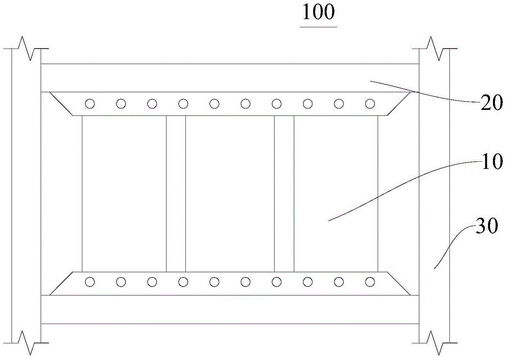
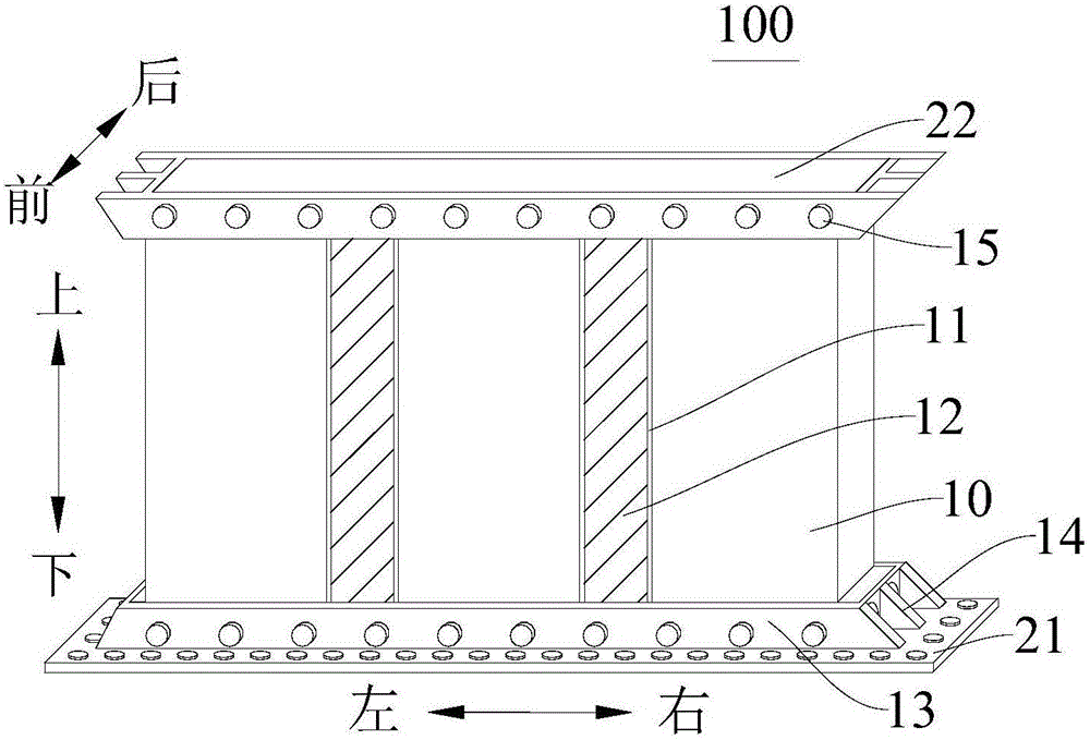
[0100] Such as Figure 1 to Figure 4 shown, combined with Figure 7, the prefabricated concrete slotted shear wall 100 includes: at least one concrete prefabricated wall panel 10, frame beams 20 and frame columns 30, the frame beams 20 include two and are arranged at intervals along the upper and lower directions, and the frame columns 30 include two and They are respectively arranged on both sides of the frame beam 20, and the upper and lower ends of each frame column 30 are respectively connected with the frame beam 20 located above and below. The frame beams 20 are connected, and the two frame columns 30 are respectively located on both sides of the precast concrete wall panel 10 , and the precast concrete wall panel 10 is provided with a plurality of first damping joints 110 arranged at intervals.

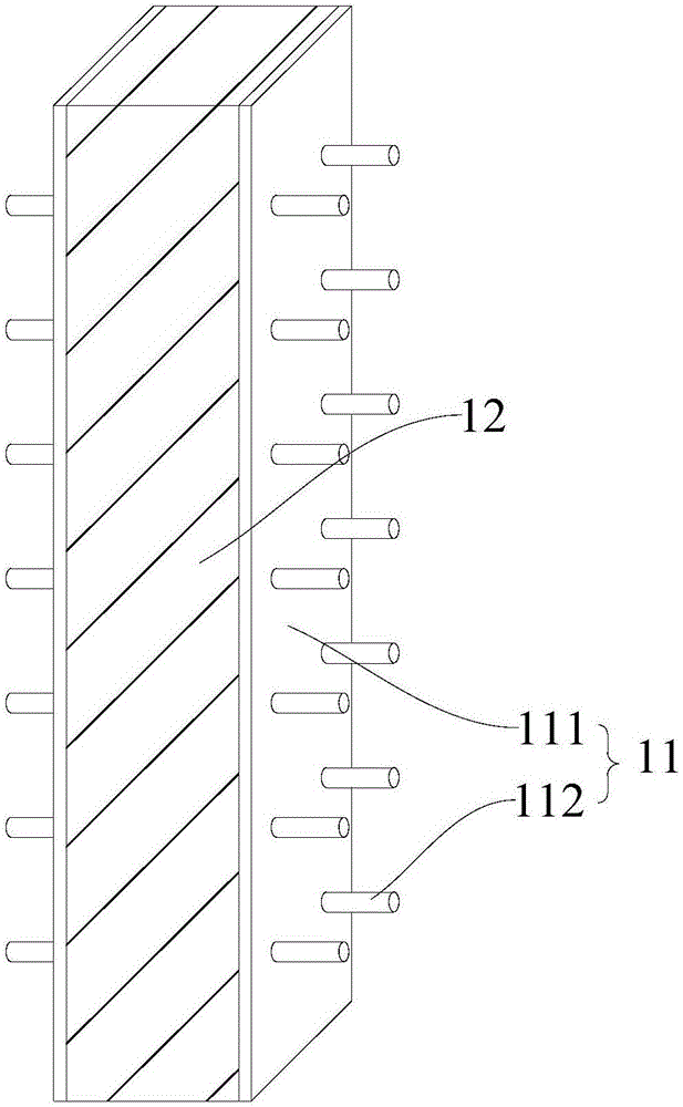
[0101] Each first damping joint 110 runs through the thickness direction of the concrete prefabricated wall panel 10 respectively, and viscoelastic energy-dissipating material...

Embodiment 2

[0107] Such as figure 1 , Figure 5 and Figure 6 shown, combined with Figure 8 , the prefabricated concrete slotted shear wall 100 includes: at least one concrete prefabricated wall panel 10, frame beams 20 and frame columns 30, the frame beams 20 include two and are arranged at intervals along the upper and lower directions, and the frame columns 30 include two and They are respectively arranged on both sides of the frame beam 20, and the upper and lower ends of each frame column 30 are respectively connected with the frame beam 20 located above and below. The frame beams 20 are connected, and the two frame columns 30 are respectively located on both sides of the concrete prefabricated wall panel 10. The concrete prefabricated wall panel 10 is provided with a plurality of spaced apart first damping joints 110, and each first damping joint 110 Respectively penetrate along the thickness direction of the concrete prefabricated wall panel 10, and each first damping joint 110...


PUM


Abstract

The invention discloses an assembly type concrete slotting shear wall which comprises frame beams, frame columns and at least one concrete prefabricated panel; the two frame beams are arranged in a spaced manner in an up-and-down manner, the two frame columns are arranged on the two sides of the frame beams, and the two ends of each frame column are connected with the frame beams located at the upper portion and the lower portion; the concrete prefabricated panel is arranged between the two frame beams and are connected with the frame beams, the two frame columns are located on the two sides of the concrete prefabricated panel, and a plurality of first damping seams arranged at intervals are formed in the concrete prefabricated panel; and each first damping seam is through in the thickness direction of the concrete prefabricated panel. According to the assembly type concrete slotting shear wall in the embodiment, the first damping seams are arranged on the concrete prefabricated panel, the wall is divided into a plurality of wall limbs with the higher depth-width ratio, the wall deforms during earthquakes, the first damping seams deform along with deformation of the wall, and therefore the non-deformability and the ductility of a building are strengthened.

Description

technical field [0001] The invention relates to the technical field of civil engineering, in particular to a prefabricated concrete slotted shear wall Background technique [0002] The development of today's building structures tends to be more and more high-rise, and the shear wall can ensure that the high-rise structure has a large lateral stiffness, so that the structure can meet the requirements of elastic deformation. The shear wall in the related art has low ductility, cannot be flexibly arranged, has a long construction period, and has a small deformation capacity. The energy consumption capacity during the deformation process is small, and it is prone to damage under the action of an earthquake, which will not only cause damage to the building , In the process of wall damage, casualties will also increase. Contents of the invention [0003] The present invention aims to solve one of the above-mentioned technical problems at least to a certain extent. [0004] For...

Claims


Application Information

Patent Timeline
Patent Type & Authority Applications(China)
IPC IPC(8): E04B2/64E04B1/98E04B1/41E04C2/30E04H9/02
CPCE04B1/41E04B2/64E04C2/30E04H9/02E04H9/025
Inventor 潘鹏沈绍冬
Owner TSINGHUA UNIV
Why Eureka
Try Eureka