Self-reset magnetic fluid damper

A magnetic fluid and damper technology, applied in building components, shockproof and other directions, can solve problems such as the inability to meet the interlayer displacement of typical frame structures, the performance of memory alloy dampers is affected by temperature, and the magnetic fluid damper has no reset ability. Avoid welding residual stress, easy to use structure, reduce the effect of welding range

Active Publication Date: 2015-11-18
BEIJING JIAOTONG UNIV
View PDF10 Cites 21 Cited by
  • Summary
  • Abstract
  • Description
  • Claims
  • Application Information

AI Technical Summary

Problems solved by technology

The shape memory alloy self-resetting damper makes full use of the superelastic properties of the shape memory alloy, and the flag-shaped hysteresis curve is full, which reduces or even eliminates the residual deformation, but the performance of the shape memory alloy is affected by temperature, and it needs to pass the shape after deformation. Memory alloy heating can make it return to the state before deformation, and the temperature rise may have adverse effects on other components of the damper; the self-restoring energy-dissipating support using prestressed steel bars cannot meet the typical frame due to the shortcoming of the small elastic deformation of prestressed steel bars The need for displacement between structural floors
Studies have shown that when the residual deformation angle of the structure after the earthquake is greater than 0.5%, the maintenance cost of the structure is greater than the reconstruction cost
Under the action of a magnetic field, the magnetorheological fluid can be transformed from a Newtonian fluid with good fluidity into a Bingham viscoplastic with high viscosity and low fluidity in milliseconds, and the magnetorheological damper made has a large output, It has the advantage

Method used


Image

  • Self-reset magnetic fluid damper
  • Self-reset magnetic fluid damper
  • Self-reset magnetic fluid damper

Examples


Embodiment Construction

[0033] In order to illustrate the present invention more clearly, the present invention will be further described below in conjunction with preferred embodiments and accompanying drawings. Similar parts in the figures are denoted by the same reference numerals. Those skilled in the art should understand that the content specifically described below is illustrative rather than restrictive, and should not limit the protection scope of the present invention.

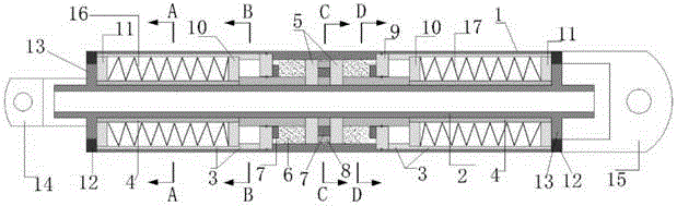
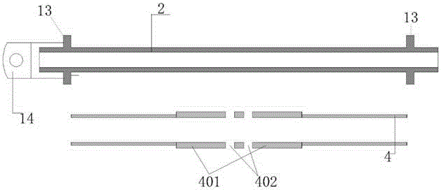
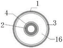
[0034] like Figure 1-Figure 7As shown, a self-resetting magnetofluid damper includes an outer tube 1, an inner tube 2, an outer tube inner sleeve 3, an inner tube outer sleeve 4, a damper piston 5, a magnetorheological fluid 6, a permanent magnet 7, and a magnetic isolation ring 8, sealing end plate 9, left side spring 16 and right side spring 17, the inner wall in the middle of the outer tube 1 is provided with a first boss 101 inwardly, and the two ends of the outer tube 1 are inwardly provided with The outer tube fixe...


PUM


Abstract

The invention discloses a self-reset magnetic fluid damper. The self-reset magnetic fluid damper comprises an outer tube, an inner tube, outer tube inner casing tubes, inner tube outer casing tubes, damper pistons, a magnetorheological fluid, permanent magnets, a magnetism isolating ring, sealing end plates, a left side spring and a right side spring, wherein first bosses are inwards arranged on the inner wall of the middle of the outer tube, outer tube fixing baffles are inwards arranged at two ends of the outer tube and are round baffles provided with round holes formed in the middles, the outer tube inner casting tubes are fixedly arranged on the inner wall of the outer tube between the first bosses and the outer tube fixing baffles, and second bosses are arranged at the ends, close to the first bosses, of the outer tube inner casting tubes. A force is transferred in the inside through the inner tube, the outer tube and the casting tubes, assembly is simple, a welding range is greatly decreased, change of the metallographic structure and mechanical performance of a steel product caused by welding and residual welding stress are avoided, and the stress performance of the members is more stable. The self-reset magnetic fluid damper is convenient to use and has higher reliability.

Description

technical field [0001] The invention relates to the technical field of magnetic fluid dampers, in particular to a self-resetting magnetic fluid damper. Background technique [0002] Earthquake is a major natural disaster faced by human beings for a long time, causing a large number of casualties and damage or collapse of buildings. When a building encounters a strong earthquake that is higher than the fortification intensity of the area, even if the overall integrity of the structure is maintained, due to excessive deformation and serious damage to some components, extensive reinforcement and repair is required, and even it can only be demolished and rebuilt. A huge waste has affected people's normal life. For this reason, a new type of disaster distribution control system-self-recovery functional structure has emerged, which can not only consume the energy transmitted to the main structure by the earthquake, realize the disaster distribution function, control the occurrenc...

Claims


Application Information

Patent Timeline
IPC IPC(8): E04B1/98
Inventor 徐龙河王坤鹏李忠献
Owner BEIJING JIAOTONG UNIV
Why Eureka
Try Eureka