Optical fiber sensor for perimeter security and protection

A technology of optical fiber sensor and mounting hole, which is applied in the direction of transmitting sensing components, converting sensor output, instruments, etc. by using optical devices, and can solve the problems that optical fiber sensors do not have the ability to move

Inactive Publication Date: 2020-10-27
杭州铭迦网络科技有限公司
View PDF0 Cites 0 Cited by
  • Summary
  • Abstract
  • Description
  • Claims
  • Application Information

AI Technical Summary

Problems solved by technology

[0004] At present, the fiber optic sensors used for perimeter security do not have the ability to move after installation. For criminals who know the terrain or sensor layout in advance, there is a greater possibility of avoiding the detection of sensors.

Method used


Image

  • Optical fiber sensor for perimeter security and protection
  • Optical fiber sensor for perimeter security and protection
  • Optical fiber sensor for perimeter security and protection

Examples


Embodiment 1

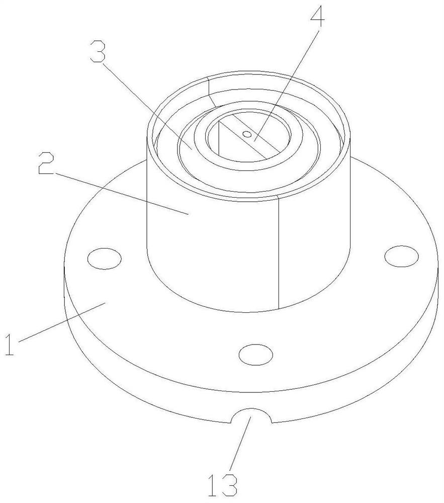
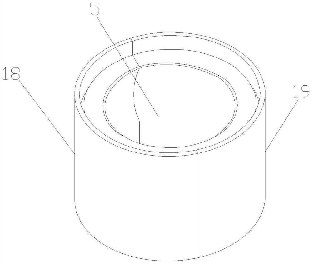
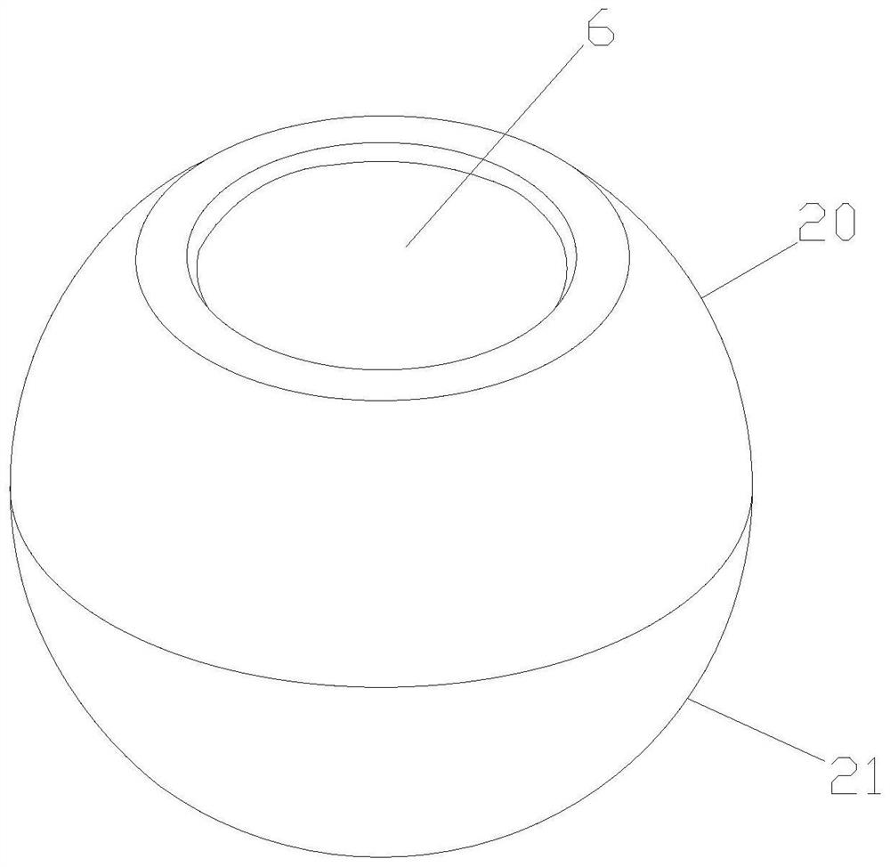
[0031] Such as Figure 1-8 As shown, a fiber optic sensor for perimeter security includes a base plate 1, an outer casing 2, a spherical inner casing 3 and a fiber optic sensor body 4, and the outer casing 2 is provided with a matching spherical inner casing 3 Joint cavity 5, the spherical inner shell 3 is installed in the joint cavity 5 and is movably connected with the outer shell 2 through the joint cavity 5, and the spherical inner shell 3 is provided with an installation hole 6 matched with the optical fiber sensor body 4 , the optical fiber sensor body 4 is installed in the installation hole 6, the outer casing 2 is provided with a connection hole (not shown), the connection hole communicates with the joint cavity 5, and the base plate 1 is provided with an electric turntable 7 and return spring 8, the middle part of the electric turntable 7 is provided with a perforation 9, the electric turntable 7 and return spring 8 are inserted into the connection hole, one end of th...

Embodiment 2

[0034] Such as Figure 1-8 As shown, a fiber optic sensor for perimeter security includes a base plate 1, an outer casing 2, a spherical inner casing 3 and a fiber optic sensor body 4, and the outer casing 2 is provided with a matching spherical inner casing 3 Joint cavity 5, the spherical inner shell 3 is installed in the joint cavity 5 and is movably connected with the outer shell 2 through the joint cavity 5, and the spherical inner shell 3 is provided with an installation hole 6 matched with the optical fiber sensor body 4 , the optical fiber sensor body 4 is installed in the installation hole 6, the outer casing 2 is provided with a connection hole (not shown), the connection hole communicates with the joint cavity 5, and the base plate 1 is provided with an electric turntable 7 and return spring 8, the middle part of the electric turntable 7 is provided with a perforation 9, the electric turntable 7 and return spring 8 are inserted into the connection hole, one end of th...


PUM


Abstract

The invention discloses an optical fiber sensor for perimeter security and protection. The optical fiber sensor comprises a bottom plate, an outer shell, a spherical inner shell and an optical fiber sensor body. A joint cavity matched with the spherical inner shell is formed in the outer shell; the spherical inner shell is mounted in the joint cavity and is movably connected with the outer shell through the joint cavity; a mounting hole matched with the optical fiber sensor body is formed in the spherical inner shell, and the optical fiber sensor body is mounted in the mounting hole; a connecting hole is formed in the outer shell, and the connecting hole is communicated with the joint cavity; an electric rotary disc and a return spring are arranged on the bottom plate; a through hole is formed in the middle of the electric rotary disc; the electric rotary disc and the reset spring are both inserted into the connecting hole; one end of the reset spring penetrates through the through hole and is fixedly connected with the bottom plate, and the other end of the reset spring is fixedly connected with the spherical inner shell; and a supporting arm is arranged on the spherical inner shell. The optical fiber sensor for perimeter security and protection has good activity ability.

Description

technical field [0001] The invention relates to an optical fiber sensor for perimeter security. Background technique [0002] The basic working principle of the optical fiber sensor is to send the optical signal from the light source to the modulator through the optical fiber, so that the parameter to be measured interacts with the light entering the modulation area, causing the optical properties of the light to change and become the modulated signal source. Send it to the photodetector through the optical fiber, and obtain the measured parameters after demodulation. [0003] Sensors are developing towards sensitivity, precision, adaptability, compactness and intelligence. In this process, fiber optic sensors, a new member of the sensor family, are favored. Optical fiber has many excellent properties, such as: anti-electromagnetic and atomic radiation interference performance, thin diameter, soft and light mechanical properties; electrical properties of insulation and non...

Claims


Application Information

Patent Timeline
Patent Type & Authority Applications(China)
IPC IPC(8): G01V8/10G01D5/26
CPCG01D5/268G01V8/10
Inventor 刘晓航周孟辉
Owner 杭州铭迦网络科技有限公司
Why Eureka
Try Eureka