
A hydraulic valve debugging system

A technology for debugging systems and hydraulic valves, applied in fluid pressure actuation system testing, fluid pressure actuation devices, mechanical equipment, etc., can solve problems such as failure to debug hydraulic valves, failures, etc., to reduce energy consumption, shorten time, and ensure correctness effect

Active Publication Date: 2018-09-25
HEFEI XIELI HYDRAULIC TECH CO LTD
View PDF7 Cites 0 Cited by
  • Summary
  • Abstract
  • Description
  • Claims
  • Application Information

AI Technical Summary

Problems solved by technology

[0006] The invention proposes a hydraulic valve debugging system, which solves the problem in the prior art that the hydraulic valve cannot be debugged in time and its faults can be solved

Method used


Image

  • A hydraulic valve debugging system
  • A hydraulic valve debugging system

Examples


Embodiment Construction

[0022] The following will clearly and completely describe the technical solutions in the embodiments of the present invention with reference to the accompanying drawings in the embodiments of the present invention. Obviously, the described embodiments are only some, not all, embodiments of the present invention. Based on the embodiments of the present invention, all other embodiments obtained by persons of ordinary skill in the art without creative efforts fall within the protection scope of the present invention.

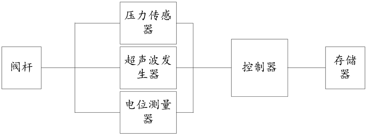
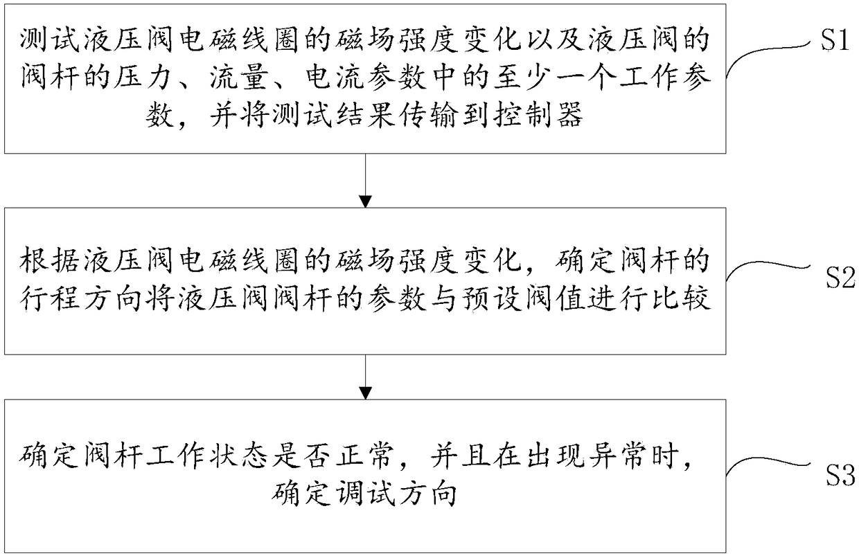
[0023] Such as Figure 1-2 As shown, the hydraulic valve debugging system includes a pressure sensor and a potentiometer connected to the valve stem of the hydraulic valve. The pressure sensor and the potentiometer are connected to a controller, and the pressure sensor and the potentiometer test the hydraulic pressure. Changes in the magnetic field strength of the valve electromagnetic coil and at least one working parameter in the pressure, flow, and current param...


PUM


Abstract

The present invention proposes a hydraulic valve debugging system, which includes a pressure sensor and a potentiometer connected to the valve stem of the hydraulic valve, the pressure sensor and the potentiometer are connected to a controller, and the pressure sensor and the potentiometer Test the magnetic field strength change of the hydraulic valve electromagnetic coil and at least one working parameter in the pressure, flow, and current parameters of the valve stem of the hydraulic valve, and transmit the test result to the controller. According to the magnetic field strength change of the hydraulic valve electromagnetic coil, Determine the stroke direction of the valve stem and compare the parameters of the valve stem of the hydraulic valve with the preset threshold value; determine whether the valve stem is in normal working condition, and determine the debugging direction when an abnormality occurs. Corresponding debug mode to solve its fault.

Description

technical field [0001] The invention belongs to the technical field of construction machinery, in particular to a hydraulic valve debugging system. Background technique [0002] At present, the slide valve mechanism is the most widely used structural form in various hydraulic valves. The slide valve is composed of three main parts: the valve body, the valve core and the valve cavity. By changing the position of the valve core in the valve body cavity, the slide valve The valve can realize the change and on-off of fluid flow. Spool valve jamming or even jamming fault is one of the most common faults and failure forms in the hydraulic system, which can generally be divided into two categories: hydraulic jamming, jamming and mechanical jamming. In layman's terms, jamming refers to the intermediate state between normal working conditions and jamming. Jamming means that the valve core cannot move. Jamming means that the valve core is difficult to move, which is not as smooth as ...

Claims


Application Information

Patent Timeline
Patent Type & Authority Patents(China)
IPC IPC(8): F15B19/00
CPCF15B19/005
Inventor 邓继周童心仲勇
Owner HEFEI XIELI HYDRAULIC TECH CO LTD
Learn More