Combined bearing and rotating shaft device using combined bearing

A combined bearing and shaft device technology, applied in the direction of bearings, bearing elements, shafts and bearings, etc., can solve the problems of hard to find woodworking end mills and high speed requirements, and achieve the effect of increasing stability and prolonging service life

Inactive Publication Date: 2017-02-15
NINGBO ZHENHAI JIEDENG APPL TECH INST
View PDF10 Cites 2 Cited by
  • Summary
  • Abstract
  • Description
  • Claims
  • Application Information

AI Technical Summary

Problems solved by technology

[0002] With the rapid development of the machinery industry, bearings are also widely used. For example, the cutter shaft bearings of endmills in woodworking machinery, although the lateral force is not large, the requirements for the speed are high, because the higher the speed, the faster the line speed, and the planer The resulting wood will be smooth. Most of the woodworking end mills on the market have a shaft diameter between 35 mm and 40 mm. It is difficult to find such a large woodworking end mill with a shaft speed exceeding 20,000 revolutions.

Method used


Image

  • Combined bearing and rotating shaft device using combined bearing
  • Combined bearing and rotating shaft device using combined bearing
  • Combined bearing and rotating shaft device using combined bearing

Examples


specific Embodiment approach 2

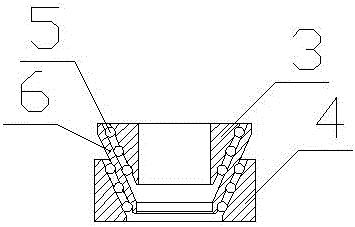
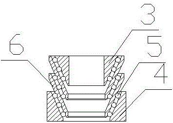
[0021] A rotating shaft device using the above-mentioned combined bearing, comprising; The main oil hole 18 is arranged in the axial direction of the axis of the rotating shaft 1. Two sets of combined bearings are arranged on the shaft body of the rotating shaft 1. The first impeller 7 and the second impeller 8 are arranged between the two sets of combined bearings. The first impeller 7 and the second The radial oil hole 10 communicating with the main oil hole 18 is arranged between the impellers 8, and the radial branch oil hole 11 communicating with the main oil hole 18 is respectively arranged on the shaft body where two sets of combined bearings are installed, and the shaft sleeve 2 Nuts 19 for fixing the composite bearing are respectively arranged at both ends of the composite bearing; the radial oil branch holes 11 are all arranged at the interval where the composite bearing is provided with rolling elements 5, and the shaft sleeve 2 is provided with an oil inlet hole 16 ...


PUM

PropertyMeasurementUnit
Taperaaaaaaaaaa

Abstract

The invention relates to a combined bearing and a rotating shaft device using the combined bearing. The combined bearing comprises an inner sleeve and an outer sleeve, and is characterized in that a middle sleeve is arranged between the inner sleeve and the outer sleeve; rolling bodies are arranged between the outer sleeve and the middle sleeve; rolling bodies are arranged between the middle sleeve and the inner sleeve; the vertical inner wall of the outer wall of the outer sleeve has the conicity; the vertical outer wall of the inner wall of the inner sleeve has the conicity; the inner wall and the outer wall of the middle sleeve have the conicity; the conicity of the inner wall of the middle sleeve is identical to the conicity of the outer wall of the inner sleeve; the conicity of the outer wall of the middle sleeve is identical to the conicity of the inner wall of the outer sleeve, so that the rolling bodies between the inner and outer sleeves can be effectively overlapped; the stability is improved; in addition, after the rolling bodies are abraded, the inner and outer sleeve can be naturally compressed; under the same condition, the speed can be doubled after the installation of one more middle sleeve through being compared with the original bearing speed; the middle sleeves have the same specification; a plurality of middle sleeves can be installed according to requirements; if one group of rolling bodies generates fault, other rolling bodies can continuously operate; the service life of the bearing is effectively prolonged.

Description

technical field [0001] The invention relates to a bearing and a rotating shaft device, in particular to a combined bearing and a rotating shaft device using the combined bearing. Background technique [0002] With the rapid development of the machinery industry, bearings are also widely used. For example, the cutter shaft bearings of endmills in woodworking machinery, although the lateral force is not large, the requirements for the speed are high, because the higher the speed, the faster the line speed, and the planer The resulting wood is smooth. Most of the woodworking end mills on the market have a shaft diameter between 35 mm and 40 mm. It is difficult to find such a large woodworking end mill with a rotating speed of more than 20,000 revolutions. [0003] In view of the above-mentioned defects, the creator of the present invention has finally obtained the present invention through long-term research and practice. Contents of the invention [0004] The object of ...

Claims


Application Information

Patent Timeline
IPC IPC(8): F16C19/54F16C33/66
CPCF16C19/54F16C33/664
Inventor 陈兆红
Owner NINGBO ZHENHAI JIEDENG APPL TECH INST
Why Eureka
Try Eureka