
Drying device for LED aluminum substrates

A technology of LED aluminum substrate and drying device, which is applied in drying, drying machine, heating device, etc., can solve the problem of unfavorable standardized baking operation of LED aluminum substrate, reduction of production and processing quality and service life of LED lamps, and excessive baking and other issues to achieve the effect of ensuring the quality of production and processing and service life

Inactive Publication Date: 2017-02-15
CHENGDU JUZHI IND DESIGN
View PDF8 Cites 7 Cited by
  • Summary
  • Abstract
  • Description
  • Claims
  • Application Information

AI Technical Summary

Problems solved by technology

But at the same time, the existing problem is that due to the limitation of structure and design, the existing drying device cannot fully and evenly bake the LED aluminum substrate placed in it, which will easily lead to partial drying. The aluminum substrate has not been baked in place, while another part of the aluminum substrate is overbaked, which is not conducive to the standardized baking operation of the LED aluminum substrate, and also greatly reduces the production and processing quality and service life of LED lamps

Method used


Image

  • Drying device for LED aluminum substrates

Examples


Embodiment Construction

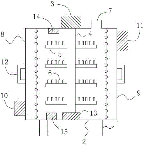
[0013] Such as figure 1 As shown, a LED aluminum substrate drying device includes a bracket 1 and a cabinet 2 arranged on the bracket 1, and a cabinet door (not shown in the figure) is also provided on the front side wall of the cabinet 2, wherein The outer top of the cabinet 2 is provided with a rotating motor 3, the output shaft of the rotating motor 3 is arranged vertically downwards and extends to the inside of the cabinet 2, and the bottom end of the output shaft of the rotating motor 3 is also connected with a vertically downward shaft. The extended rotating shaft 4 is also fixedly sleeved with a plurality of annular trays 5 on the rotating shaft 4; a plurality of tray ventilation holes are provided on the annular tray 5, and a plurality of vertical trays are evenly distributed on the top plane of the annular tray 5. The needle-shaped protrusion 6 extending upwards (and the smaller the diameter of the needle-shaped protrusion 6, the better, so that the distance between t...


PUM


Abstract

The invention relates to a drying device for LED aluminum substrates. The drying device comprises a support and a cabinet body; a cabinet door is arranged on the front side wall of the cabinet body; a rotating motor is arranged at the top end of the outer part of the cabinet body; the bottom end of an output shaft of the rotating motor is connected with a rotating shaft extending vertically downwards; the rotating shaft is fixedly sleeved with circular trays; tray ventilating holes are formed in the circular trays; needle-like bulges extending vertically upwards are uniformly distributed on top planes of the circular trays; an exhaust port is formed in the top wall of the cabinet body; a left cavity and a right cavity are formed in the left side and the right side of the cabinet body respectively; multiple left ventilating holes and multiple right ventilating holes are uniformly formed in the left side wall and the right side wall of the cabinet body; a left air heater is arranged at the lower part of the left side of the left cavity; a right air heater is arranged at the upper part of the right side of the right cavity; an air outlet of the left air heater communicates with the left cavity; and an air outlet of the right air heater communicates with the right cavity. With the adoption of the structure, the aluminum substrates placed in the device can be dried sufficiently and uniformly, so that the production and machining quality and the service life of LED lamps are greatly guaranteed.

Description

technical field [0001] The invention relates to an LED aluminum substrate drying device. Background technique [0002] In the production process of LED lamps, it is often necessary to use a drying device to dry the LED aluminum substrate. But at the same time, the existing problem is that due to the limitation of structure and design, the existing drying device cannot fully and evenly bake the LED aluminum substrate placed in it, which will easily lead to partial drying. The aluminum substrate has not been baked in place, while another part of the aluminum substrate is overbaked, which is not conducive to the standardized baking operation of the LED aluminum substrate, and also greatly reduces the production and processing quality and service life of the LED lamps. Contents of the invention [0003] In order to overcome the above deficiencies in the prior art, the technical problem to be solved by the present invention is to provide an LED aluminum substrate drying device...

Claims


Application Information

Patent Timeline
Patent Type & Authority Applications(China)
IPC IPC(8): F26B11/18F26B25/18F26B23/04F26B25/12F26B21/00
CPCF26B11/18F26B21/004F26B23/04F26B25/12F26B25/185
Inventor 文国栋
Owner CHENGDU JUZHI IND DESIGN
Learn More