Energy-saving drying device for inner wall of pipeline

A drying device and energy-saving technology, applied in drying, drying machine, drying gas layout, etc., can solve the problem that the inner wall of the pipeline cannot be fully dried.

Pending Publication Date: 2021-05-18
住重福惠动力机械有限公司
View PDF5 Cites 0 Cited by
  • Summary
  • Abstract
  • Description
  • Claims
  • Application Information

AI Technical Summary

Problems solved by technology

[0007] The purpose of the present invention is to provide an energy-saving drying device for the inner wall o...

Method used


Image

  • Energy-saving drying device for inner wall of pipeline
  • Energy-saving drying device for inner wall of pipeline
  • Energy-saving drying device for inner wall of pipeline

Examples


Embodiment 1

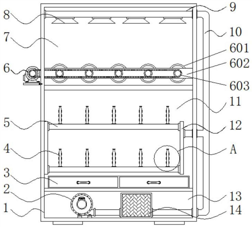
[0025] Example 1: See Figure 1-4 , an energy-saving drying device for the inner wall of a pipeline, including a body 1 and a first chamber 7, the inside of the body 1 is respectively provided with a first chamber 7, a second chamber 11 and a third chamber 13, the second The bottom end inside the three-chamber 13 is fixedly connected with a fan 2, the model of the fan 2 is DF, the output end of the fan 2 is fixedly connected with a heater 14, the model of the heater 14 is YC01, and the output end of the heater 14 is fixed The delivery pipe 10 is connected, the bottom end inside the second chamber 11 is fixedly connected with the water collecting structure 3, the bottom end inside the first chamber 7 is provided with a transmission mechanism 6, and the top end inside the first chamber 7 is fixedly connected with a second An exhaust pipe 9, the bottom end of the first exhaust pipe 9 is fixedly connected with four sets of air outlets 8, and the inside of the second chamber 11 is ...

Embodiment 2

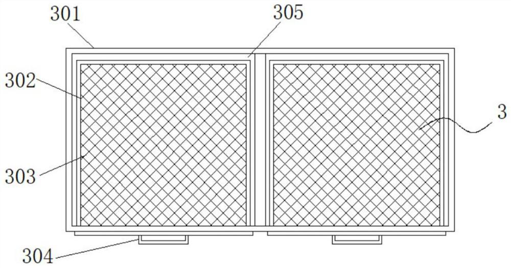
[0029] Embodiment 2: The water collecting structure 3 is composed of a water collecting box 301, a pumping box 302, a mesh plate 303, a handle 304 and a reserved groove 305. The water collecting box 301 is fixedly connected to the bottom end inside the second chamber 11, and the water collecting Two sets of reserved grooves 305 are arranged inside the box 301, and a drawing box 302 is arranged inside the reserved groove 305, the top of the drawing box 302 is fixedly connected with a mesh plate 303, and one end of the drawing box 302 is fixedly connected with a handle 304;

[0030] The drawer box 302 is provided with two groups and is symmetrically distributed with respect to the vertical center line of the water collection box 301. The width outside the drawer box 302 is smaller than the width inside the reserved groove 305, and the drawer box 302 is embedded in the reserved groove 305;

[0031] Specifically, such as figure 1 and image 3 As shown, the inner wall of the pipe ...

Embodiment 3

[0032] Embodiment 3: The transmission mechanism 6 is composed of a roller 601, a fixed plate 602, a belt 603 and a drive motor 604. The fixed plate 602 is fixedly connected to both ends of the first chamber 7, and there are five sets of flexible connections between the fixed plates 602. The roller 601 is fixedly connected with a drive motor 604 on one side of the body 1. The model of the drive motor 604 is Y90S-2, and the output end of the drive motor 604 is movably connected with a belt 603 through a coupling;

[0033] The inner side of the belt 603 is flexibly connected to the outside of one end of the roller 601;

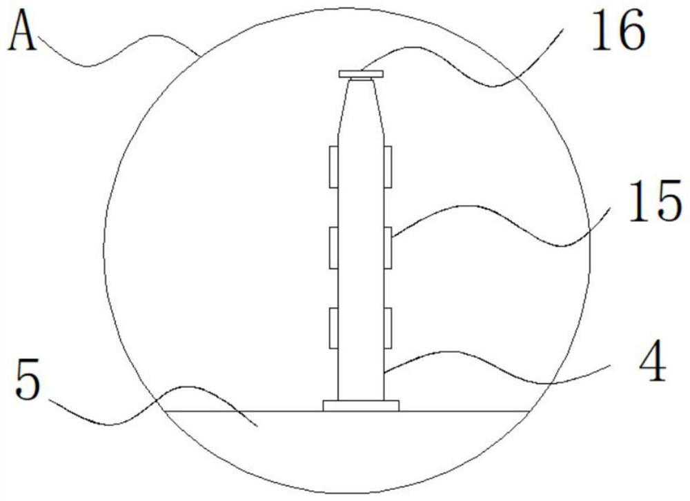
[0034] Specifically, such as figure 1 and Figure 4As shown, when the device dries a pipe with a larger diameter and width, the pipe can be placed in the first chamber 7 inside the body 1, the pipe is placed between the rollers 601, and then the drive motor 604 uses the belt 603 to drive the five The group of rollers 601 rotate slowly together, and the pipe can...


PUM


Abstract

The invention discloses an energy-saving drying device for the inner wall of a pipeline, and particularly relates to the technical field of pipeline drying. The energy-saving drying device comprises a machine body and a first cavity, wherein the first cavity, a second cavity and a third cavity are formed in the machine body, the bottom end in the third cavity is fixedly connected with a fan, and the output end of the fan is fixedly connected with a heater. According to the energy-saving drying device, drying pipes, air conveying pipes, a second exhaust pipe, air outlets and silica gel sheets are arranged, the inner walls of some pipelines with small pipe orifice diameters are difficult to dry, the drying pipes are arranged in several sets on the to-be-dried drying pipeline, the drying pipes are sleeved with the pipeline firstly, then the fan and the heater convey hot air into the conveying pipes, and the hot air in the conveying pipes is conveyed into the drying pipes through the second exhaust pipe and then is discharged from the air outlets of the drying pipes to dry the inner wall of the pipeline. According to the structure, the inner wall of the pipeline is directly dried, and the situation that the inner wall of the pipeline is insufficiently dried is avoided.

Description

technical field [0001] The invention relates to the technical field of pipeline drying, in particular to an energy-saving drying device for the inner wall of a pipeline. Background technique [0002] The materials and types of pipes are relatively diverse. Whether it is ceramic pipes or plastic pipes, pipe drying devices are required during processing. There are still some shortcomings in existing pipe drying devices that need to be improved. For example, the device is used There are fewer drying outlets, so that the inner wall of the pipe cannot be fully dried, or the water inside the pipe and the water generated inside the device accumulate inside the device, which may easily cause a short circuit in the device circuit. [0003] In the process of realizing the present invention, the inventors have found that at least the following problems in the prior art have not been resolved: [0004] (1) The traditional energy-saving drying device used for the inner wall of the pipel...

Claims


Application Information

Patent Timeline
IPC IPC(8): F26B15/12F26B21/00F26B25/00F26B25/02F26B25/18
CPCF26B15/122F26B21/004F26B21/001F26B21/008F26B25/185F26B25/02F26B25/00
Inventor 丁晓明吴学军李绍迎
Owner 住重福惠动力机械有限公司
Why Eureka
Try Eureka