Radio transceiver test shielding box

A technology for radio transceivers and transceivers, which is applied in the field of radio transceiver test shielding boxes, and can solve problems such as large coupling methods, incomplete test coverage, and inability to fully reflect the technical indicators of radio transceivers.

Active Publication Date: 2017-02-15
GUIZHOU AEROSPACE ELECTRONICS TECH CO LTD
View PDF9 Cites 13 Cited by
  • Summary
  • Abstract
  • Description
  • Claims
  • Application Information

AI Technical Summary

Problems solved by technology

Generally, the antenna coupling cover is used to receive and feed the microwave signals emitted by the antenna. However, this coupling method has a large microwave leakage, so accurate testing cannot be performed when there is strong reflection in the test environment. At this time, only incomplete transmission and reception can be performed. The precise test of the machine (that is, only the transceiver), the microwave transmission is carried out from the high-frequency port of the transceiver with a high-frequency adapter
Obviously, the incomplete transceiver test cannot reflect the indicators of the antenna, cannot fully reflect the technical indicators of the radio transceiver, and the test coverage is incomplete
[0004] Since the temperature test box is surrounded by metal materials, there is a strong reflection of microwaves, so when conducting temperature tests, only incomplete transceivers can be accurately tested.

Method used


Image

  • Radio transceiver test shielding box

Examples


Embodiment Construction

[0022] The technical solution of the present invention is further described below, but the scope of protection is not limited to the description.

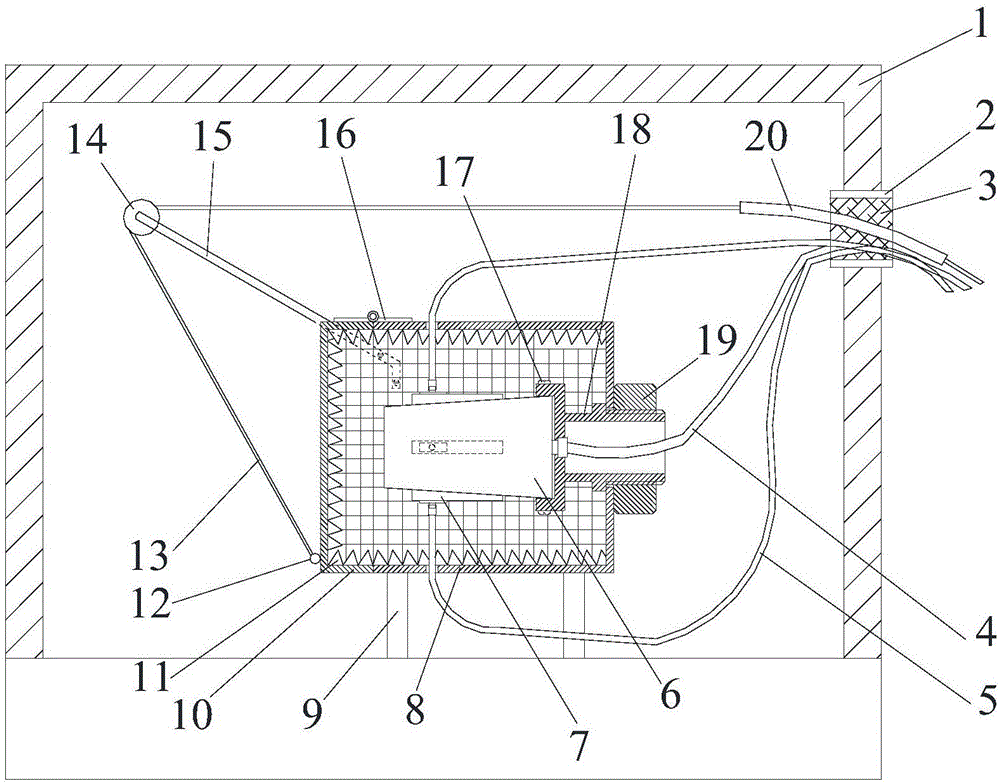
[0023] Such as figure 1 A kind of radio transceiver test shielding box shown, comprises test box 1, low-frequency cable 4, high-frequency cable 5, coupling cover 7, inner box body 8, box cover 10, stay rope 13, pulley 14, support 15, Hinge 16, mounting seat 18; The inner center position of described test box 1 is fixed with inner box body 8 by box foot 9, and the center position in inner box body 8 is provided with the transceiver 6 to be tested, and transceiver 6 is fixed on the mounting seat 18; the side of the front end of the test box 1 is provided with a lead-out hole 2, the transceiver 6 leads out the low-frequency cable 4 toward the front end of the lead-out hole 2, and the low-frequency cable 4 passes through the mounting seat 18 and the lead-out hole 2 to lead out of the test box 1 in turn , the mounting seat 18 passes th...


PUM


Abstract

The invention provides a radio transceiver test shielding box comprising a test box, a low frequency electric cable, a high frequency electric cable, a coupling cover, an inner box body, a box cover, a pull rope, a pulley wheel, a support rack, a hinge and an installation seat, wherein the inner box body is fixed at a central position of an inner part of the test box via box feet, the central position of an inner part of the inner box body is provided with a transceiver to be tested, the transceiver is fixed on the installation seat, and a front end side face of the test box is provided with a lead-out hole; the low frequency electric cable is led out from a front end, facing toward the lead-out hole, of the transceiver; the low frequency electric cable is led out from the test box after orderly running through the installation seat and the lead-out hole; the installation seat is fixed at a middle part of a side face, facing toward the lead-out hole, of the inner box body after running through the same. Via the radio transceiver test shielding box, test indexes of a complete radio transceiver can be prevented from being affected by microwave leakage signals after the microwave leakage signals are reflected via surrounding environment, and a problem that the complete radio transceiver cannot be precisely tested during temperature test operation can be solved.

Description

technical field [0001] The invention relates to a test shielding box for a radio transceiver. Background technique [0002] When the radio transceiver is subjected to a temperature test, it is necessary to place the radio transceiver in a temperature test chamber for testing. Since the temperature in the temperature test box needs to be kept constant during the test, the temperature test box cannot be opened during the test, and the test cable can only be led out of the temperature test box for testing. The test cable of the radio transceiver is composed of a high frequency cable and a low frequency cable. The high frequency cable is used to transmit microwave signals, and the low frequency cable is used to transmit low frequency signals. The complete radio transceiver consists of a transceiver and an antenna. The transceiver generates microwave signals and processes echo signals. The antenna is used to transmit the microwave signals generated by the transceiver to space an...

Claims


Application Information

Patent Timeline
Patent Type & Authority Applications(China)
IPC IPC(8): G01R1/18G01S7/40
CPCG01R1/18G01S7/4004
Inventor 江茂军
Owner GUIZHOU AEROSPACE ELECTRONICS TECH CO LTD
Why Eureka
Try Eureka