
Signal detection system

A signal detection and signal technology, applied in the field of signal detection, can solve the problems of relatively high precision and cost requirements, and achieve the effect of overcoming the high cost and high-precision detection of measuring devices

Inactive Publication Date: 2017-02-15
PHICOMM (SHANGHAI) CO LTD
View PDF4 Cites 2 Cited by
  • Summary
  • Abstract
  • Description
  • Claims
  • Application Information

AI Technical Summary

Problems solved by technology

In order to detect weak signals of this level, most of the existing technologies use high-precision and high-bit analog-to-digital converter (Analog To Digital Converter, ADC) chips for direct sampling. This detection method has relatively high requirements for equipment precision and cost. , it is necessary to use sophisticated detection equipment to collect such a weak electrical signal

Method used


Image

  • Signal detection system
  • Signal detection system
  • Signal detection system

Examples


Embodiment Construction

[0019] In order to more clearly illustrate the embodiments of the present invention or the technical solutions in the prior art, the specific implementation manners of the present invention will be described below with reference to the accompanying drawings. Obviously, the accompanying drawings in the following description are only some embodiments of the present invention, and those skilled in the art can obtain other accompanying drawings based on these drawings and obtain other implementations.

[0020] In order to make the drawing concise, each drawing only schematically shows the parts related to the present invention, and they do not represent the actual structure of the product. In addition, to make the drawings concise and easy to understand, in some drawings, only one of the components having the same structure or function is schematically shown, or only one of them is marked. Herein, "a" not only means "only one", but also means "more than one".

[0021] The signal...


PUM


Abstract

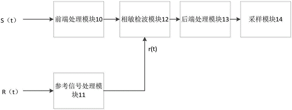
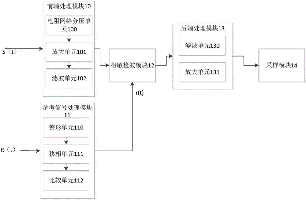
The invention discloses a signal detection system. The signal detection system comprises a front-end processing module used for receiving a to-be-detected signal, carrying out voltage division, amplification and filtering processing on the to-be-detected signal and outputting the processed signal, a reference signal processing module used for receiving a reference signal, carrying out shaping, phase shift and comparison processing on the reference signal to generate a square wave signal and outputting the square wave signal, a phase-sensitive detection module used for receiving the to-be-detected signal outputted by the front-end processing module and the square wave signal outputted by the reference signal processing module, carrying out phase-sensitive detection on the to-be-detected signal according to the square wave signal to generate a phase-sensitive detection signal and then outputting the phase-sensitive detection signal, a back-end processing module used for receiving the phase-sensitive detection signal, carrying out filtering and amplification processing on the phase-sensitive detection signal and then outputting the processed phase-sensitive detection signal, and a sampling module used for carrying out sampling quantification for the phase-sensitive detection signal outputted by the back-end processing module after processing to acquire an amplitude value of the phase-sensitive detection signal.

Description

technical field [0001] The invention relates to the technical field of signal detection, in particular to a technology for detecting weak signals based on an analog multiplier. Background technique [0002] Most of the signals in nature are analog signals, including light, sound, pressure, heat, etc. It is impossible for such signals to be processed by the processor, and they must be converted by sensors to convert them into If the electrical signal that is easy to analyze and process is processed, if the original signal is very weak, the generated electrical signal will also be very weak, generally at the microvolt level. In order to detect weak signals of this level, most of the existing technologies use high-precision and high-bit analog-to-digital converter (Analog To Digital Converter, ADC) chips for direct sampling. This detection method has relatively high requirements for equipment precision and cost. , It is necessary to use sophisticated detection equipment to col...

Claims


Application Information

Patent Timeline
IPC IPC(8): G01R1/30G01R29/00G01D5/14
CPCG01R1/30G01D5/14G01R29/00
Inventor 孙嵩
Owner PHICOMM (SHANGHAI) CO LTD
Learn More