
A Loss Identification and Prediction Method of Experimental Mode Frequency

An experimental modal and modal frequency technology, applied in the field of mechanical vibration, can solve the problems of high equipment cost, low debugging efficiency, and long calculation time, and achieve the effects of low requirements, improved debugging efficiency, and reduced calculation amount and calculation time

Active Publication Date: 2019-05-10
KUNMING UNIV OF SCI & TECH
View PDF2 Cites 0 Cited by
  • Summary
  • Abstract
  • Description
  • Claims
  • Application Information

AI Technical Summary

Problems solved by technology

This method overcomes the problems of high equipment cost and low debugging efficiency in multi-point excitation and multi-point picking, and also overcomes the large amount of calculation and long calculation time in the correlation analysis between the calculated mode shape and the experimental mode shape. The problem of low identification efficiency

Method used


Image

  • A Loss Identification and Prediction Method of Experimental Mode Frequency
  • A Loss Identification and Prediction Method of Experimental Mode Frequency
  • A Loss Identification and Prediction Method of Experimental Mode Frequency

Examples


Embodiment 1

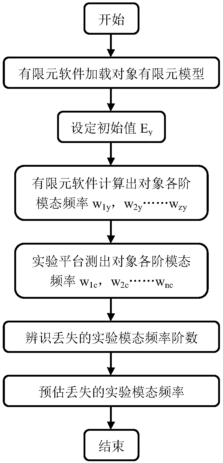
[0036] Example 1: Such as figure 1 As shown, an experimental modal frequency loss identification and estimation method includes the following specific steps:

[0037] Step 1 In the finite element software, import the finite element model of the loaded object;

[0038] Step 2 In the finite element software, set the Young's modulus E of the finite element model y ;

[0039] Step 3 In the finite element software, calculate the modal frequency w of the object 1y , W 2y …, w py ,...W zy , Where z is the maximum order of the modal frequency of the object calculated by the finite element software;

[0040] Step 4 Through the experimental platform, measure the modal frequency w of the object 1c , W 2c …, w ic ,...W nc , Where n is the maximum order of the modal frequency of the object measured by the experimental platform, and n≤z;

[0041] Step 5 Identify the missing experimental modal frequency order

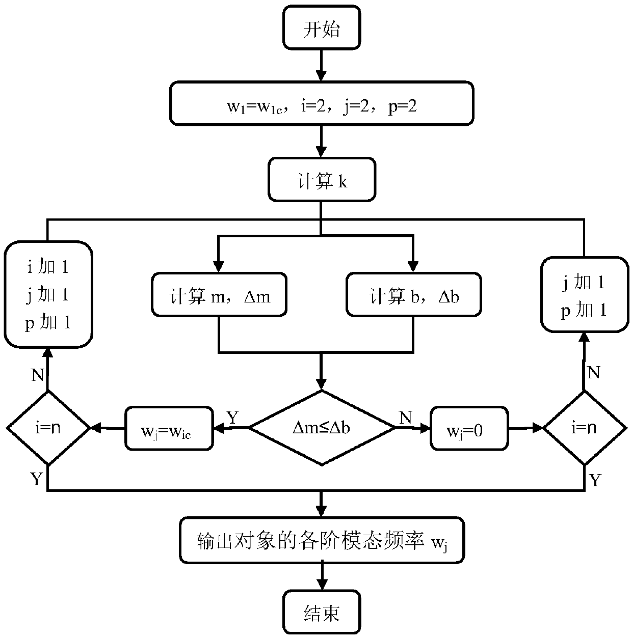
[0042] Such as figure 2 As shown, 5.1 calculate k, where k=w 1c / w 1y ;

[0043] 5.2 L...

Embodiment 2

[0054] Embodiment 2: Step 1 In the finite element software, import the finite element model of the loaded object.

[0055] Step 2 In the finite element software, set the Young's modulus Ey of the finite element model = 1010Pa.

[0056] Step 3 In the finite element software, calculate the modal frequency w of the object 1y = 10.2 Hz, w 2y = 15.4 Hz, w 3y = 22.6 Hz, w 4y =32.1Hz, w 5y = 53.6 Hz, w 6y = 66.7 Hz, w 7y = 72.6 Hz.

[0057] Step 4 Through the experimental platform, measure the modal frequency w of the object 1c =101.3Hz, w 2c = 153.6 Hz, w 3c =319.7Hz, w 4c =535.5Hz, w 5c = 666.6 Hz.

[0058] Step 5 Identify the missing experimental modal frequency order

[0059] 5.1 Let w 1 =w 1c , J=2, i=2, p=2, where w j Is the modal frequency of the object, j is the subscript of the modal frequency of the object, i is the subscript of the measured modal frequency of the object, and p is the subscript of the modal frequency of the calculated object;

[0060] 5.2 Calculate k according to the ...


PUM


Abstract

The invention relates to a loss identification and estimation method of experiment modal frequency, and belongs to the technical field of mechanical vibration. The purpose of the invention is to provide a loss identification and estimation method of experiment modal frequency. In accordance with strong positive correlation of calculation modal frequency and the experiment modal frequency, correlation analysis is carried out on the experiment modal frequency and the corresponding calculation modal frequency to identify an order of loss of the experiment modal frequency, and meanwhile the experiment modal frequency of the corresponding loss is estimated. By adoption of the method, the problems of high equipment cost and low debugging efficiency in multipoint excitation and multipoint pickup are overcome, and the problems of large calculated amount, long calculation time and low identification efficiency in the correlation analysis of the calculation modal frequency and the experiment modal frequency are also overcome.

Description

Technical field [0001] The invention relates to a method for identifying and predicting the loss of experimental modal frequencies, and belongs to the technical field of mechanical vibration. Background technique [0002] In the process of obtaining the experimental modal frequency of the object through experimental measurement, if the excitation point or the pick-up point is located at the node of a certain modal shape, or the noise of the experimental measurement platform system has a certain modal frequency Obvious interference effects will cause the loss of experimental modal frequency orders. [0003] At present, there are two main solutions to the loss of the experimental modal frequency order. One is to use multi-point excitation and multi-point pickup on the object. This method can avoid the loss of the experimental modal frequency order, but this method It is suitable for large and medium-sized structures and requires large excitation energy. At the same time, each excite...

Claims


Application Information

Patent Timeline
Patent Type & Authority Patents(China)
IPC IPC(8): G06F17/50
CPCG06F30/23
Inventor 刘孝保刘洋刘璐
Owner KUNMING UNIV OF SCI & TECH
Learn More