
Differential protection method based on adaptive ratio braking curve

A differential protection and ratio braking technology, applied in emergency protection circuit devices, electrical components, etc., can solve the problems of easy misoperation, reduced sensitivity, low transformer sensitivity, etc.

Inactive Publication Date: 2017-02-15
BEIJING SIFANG JIBAO AUTOMATION
View PDF3 Cites 11 Cited by
  • Summary
  • Abstract
  • Description
  • Claims
  • Application Information

AI Technical Summary

Problems solved by technology

[0004] Practice shows that the application of two-fold line characteristic differential protection on generators, transmission lines and other components has achieved good results, but there are some problems when it is applied to transformers: it is affected by restorative inrush current and current transformer (CT ) due to the influence of the transmission error, the misoperation phenomenon of the two-fold line characteristic differential protection after the external fault is removed occurs from time to time
[0005] The three-fold line braking characteristic can well solve the problem of misoperation of the protection after the external fault is removed, but it brings the side effect of low sensitivity when there is a slight inter-turn fault inside the transformer.
The horizontal section of the two-fold line characteristic ensures the sensitivity of the slight turn-to-turn fault inside the transformer, but it makes the protection prone to misoperation when the external fault is removed; although the three-fold line characteristic makes the protection have higher safety, it reduces the sensitivity.

Method used


Image

  • Differential protection method based on adaptive ratio braking curve
  • Differential protection method based on adaptive ratio braking curve
  • Differential protection method based on adaptive ratio braking curve

Examples


Embodiment Construction

[0055] The technical solutions of the present invention will be further described below in conjunction with the accompanying drawings and through specific implementation methods.

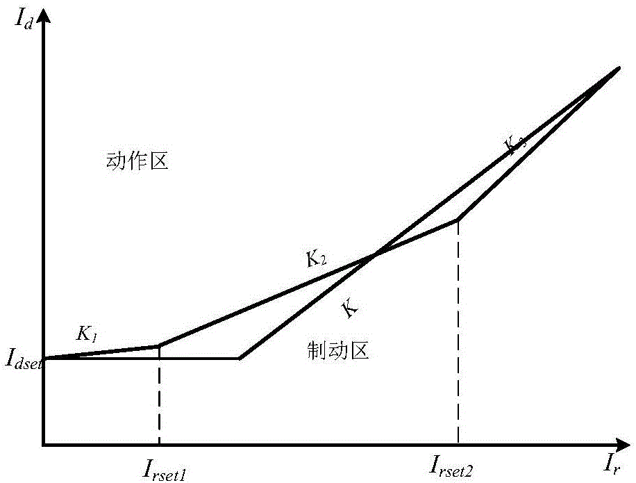
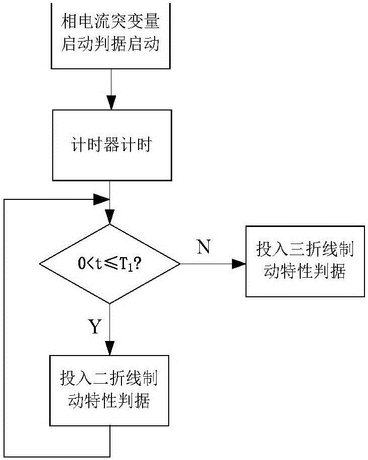
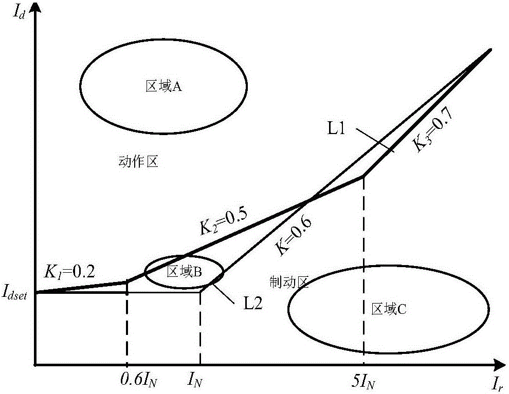
[0056] The differential protection method based on the self-adaptive ratio braking curve proposed by the present invention simultaneously adopts a three-fold ratio braking curve with higher safety and a two-fold ratio braking curve with higher sensitivity (such as figure 1 As shown), it overcomes the disadvantage that the conventional differential protection only uses a single braking characteristic, which leads to the inability to take into account the sensitivity and safety of the protection. The logical coordination relationship between the two characteristic curves is: the start of the phase current sudden change start criterion is used as the timing starting point, T 1 The time protection automatically switches on the two-fold line braking characteristic with high sensitivity, which is used to ...


PUM


Abstract

The invention provides a differential protection method based on an adaptive ratio braking curve. The method comprises the following steps: sampling three-phase current on each side of a transformer; calculating a differential current phasor value and a braking current phasor value; performing phase current break variable calculation on each sampled phase current instantaneous value, and judging whether a phase current break variable criterion is satisfied; after the break variable criterion is satisfied, starting a timer to start timing, and inputting two-broken-line braking characteristics within a set time T1; and logging out the two-broken-line braking characteristics after the time T1, and inputting three-broken-line braking characteristics with stronger braking property. By adoption of the differential protection method provided by the invention, the objective of preventing maloperation by the three-broken-line braking characteristics with stronger braking property after removing an internal fault by using the two-broken-line braking characteristics with higher sensitivity and removing an external fault is achieved, the defect that both of the sensitivity and the safety of the protection cannot be achieved resulting from that a single braking curve is adopted in conventional differential protection is overcome, and the protection action performance is improved, therefore the differential protection method has a great engineering application value.

Description

technical field [0001] The invention belongs to the field of relay protection of electric power system, and more specifically relates to a differential protection method of an adaptive ratio braking curve suitable for microcomputer protection. Background technique [0002] The principle of current differential protection is based on Kirchhoff's current law, and it acts on the difference between the inflow current and outflow current of the protected element. Delayed removal of various short-circuit faults in the area, so it is widely used as the main protection of various components. [0003] In differential protection, the ratio braking characteristic with broken line is usually used, the most basic is the two broken line braking characteristic. The braking characteristic of the two-fold line is composed of a non-braking horizontal section and a braking oblique section. The setting of the horizontal section is to prevent the protection from malfunctioning when the measured...

Claims


Application Information

Patent Timeline
Patent Type & Authority Applications(China)
IPC IPC(8): H02H7/045
CPCH02H7/045
Inventor 黄少锋李珊珊肖远清张良张恒祥戴丽君赵俊磊
Owner BEIJING SIFANG JIBAO AUTOMATION
Learn More