Fiber bragg grating soil pressure sensor

An earth pressure sensor and fiber grating technology, applied in the sensor field, can solve the problems of inability to compensate for temperature effects, uneven force, measurement errors, etc.

Active Publication Date: 2020-10-30
YANGTZE OPTICAL FIBRE & CABLE CO LTD
View PDF22 Cites 3 Cited by
  • Summary
  • Abstract
  • Description
  • Claims
  • Application Information

AI Technical Summary

Problems solved by technology

[0003] The patent "Fiber Bragg Grating Earth Pressure Sensor" (application number 201911242132.4) discloses an earth pressure sensor that measures the pressure by measuring the tensile strain of the elastic beam. Although the design uses a temperature-compensating fiber grating, it can offset part of the temperature caused by However, the fluid filled in the upper cavity will expand with heat and contract with cold, which will still affect the pressure measurement. At the same time, it adopts an X-shaped frame structure, and the earth pressure is transmitted to the elastic beam through the partition. When the X-shaped frame is clamped When the angle changes, the ratio of the force of the elastic beam to the earth pressure also changes (related to the included angle), which is not a linear relationship, and there will be a principle error in the measurement
[0004] The patent "A Fiber Bragg Grating Earth Pressure Sensor with Temperature Compensation Function" (Application No. 201910957418.4) discloses a sensor capable of measuring temperature and earth pressure. Two optical fiber gratings, one is placed in a cavity with good thermal conductivity, which can measure the temperature of the outside world, and the other is separated by a layer of heat-insulating film, and only measures pressure. This patent can only measure temperature and pressure at the same time. Due to the two optical fiber gratings The temperature environment at the place is different, and it cannot compensate the influence of temperature on the fiber Bragg grating for measuring pressure. As a result, the pressure value measured by the fiber Bragg grating for measuring pressure will still be affected by temperature.
[0005] The patent "A Fiber Bragg Grating Earth Pressu

Method used


Image

  • Fiber bragg grating soil pressure sensor
  • Fiber bragg grating soil pressure sensor
  • Fiber bragg grating soil pressure sensor

Examples


Embodiment Construction

[0033] In order to make the object, technical solution and advantages of the present invention clearer, the present invention will be further described in detail below in conjunction with the examples. It should be understood that the specific embodiments described here are only used to explain the present invention, not to limit the present invention. In addition, the technical features involved in the various embodiments of the present invention described below can be combined with each other as long as they do not constitute a conflict with each other.

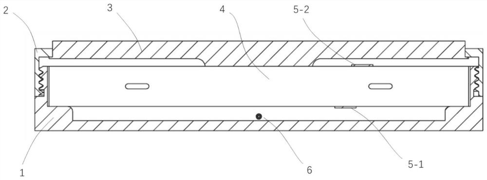
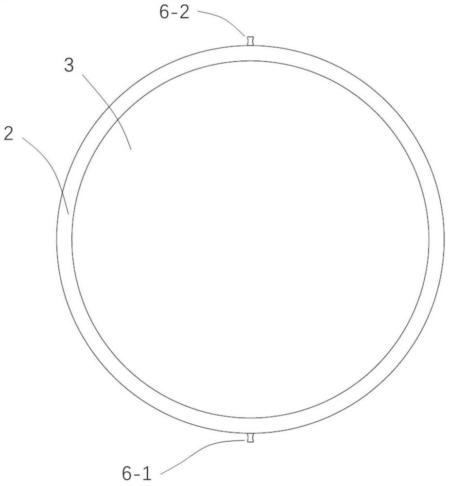
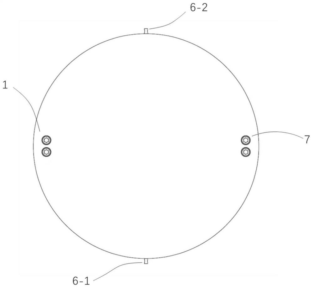
[0034] The fiber grating earth pressure sensor provided by the present invention includes an end cover, a pressure plate, a strain beam and a base; the strain beam includes: a middle part for transmitting pressure, two ends for fixing, and two sections between the middle part and one end The two ends of the strain beam are erected on the base, and the middle part is suspended in the air; the center of the pressure plate has...


PUM

PropertyMeasurementUnit
Heightaaaaaaaaaa
Lengthaaaaaaaaaa

Abstract

The invention discloses a fiber bragg grating soil pressure sensor which comprises a pressure disc, a strain beam and a base. The strain beam comprises a middle part used for conducting pressure, twoends used for fixing and two cantilevers located between the middle part and the two ends respectively, the two ends of the strain beam are erected on the base, and the middle of the strain beam is suspended. The center of the pressure disc is provided with a downward boss which is crimped with the middle part of the strain beam; and at least one cantilever of the strain beam is pasted with one ormore fiber bragg gratings, and the fiber bragg grating sensor is used for sensing deformation of the cantilever caused by the pressure conducted to the middle part of the strain beam by the boss of the pressure disc. According to the fiber bragg grating soil pressure sensor provided by the invention, the strain beam is adopted to replace a strain film, so that errors caused by uneven pressure distribution can be reduced.

Description

technical field [0001] The invention belongs to the field of sensors, and more specifically relates to a fiber grating earth pressure sensor Background technique [0002] The earth pressure sensor is mainly used to measure the soil pressure change of the buried point in soft soil and fill, and also can measure the surface contact pressure of the soil on the retaining wall, anti-slide pile, etc. The earth pressure sensor currently on the market mainly measures the pressure indirectly by measuring the strain of the stressed beam, and is divided into two types: the resistance strain gauge type and the fiber grating type from the sensitive element. Resistance strain earth pressure sensors have weak output signals, are susceptible to electromagnetic interference, and are difficult to network. Fiber Bragg grating earth pressure sensors have high resolution, are free from electromagnetic interference, and have stable performance. They are more and more used in civil engineering. ...

Claims


Application Information

Patent Timeline
IPC IPC(8): G01L1/24
CPCG01L1/242G01L1/247
Inventor 张金银李立彤洪登杭常东方勇熊良明
Owner YANGTZE OPTICAL FIBRE & CABLE CO LTD
Why Eureka
Try Eureka