Magnetic sensor system

Inactive Publication Date: 2005-08-04
BERNSTEIN AG
View PDF2 Cites 4 Cited by
  • Summary
  • Abstract
  • Description
  • Claims
  • Application Information

AI Technical Summary

Benefits of technology

[0009] Preferably, a temperature measuring device is provided for temperature compensation of the detection where the sensor is essentially dependent on the temperature. The reason is that sensors, particularly Hall sensors, are temperature-depend

Problems solved by technology

However, inductive sensors have the disadvantage that they may be influenced by non-ferromagnetic metallic system parts, such as aluminum.
The minimal demands on the switching frequenc

Method used


Image

  • Magnetic sensor system
  • Magnetic sensor system
  • Magnetic sensor system

Examples


Example

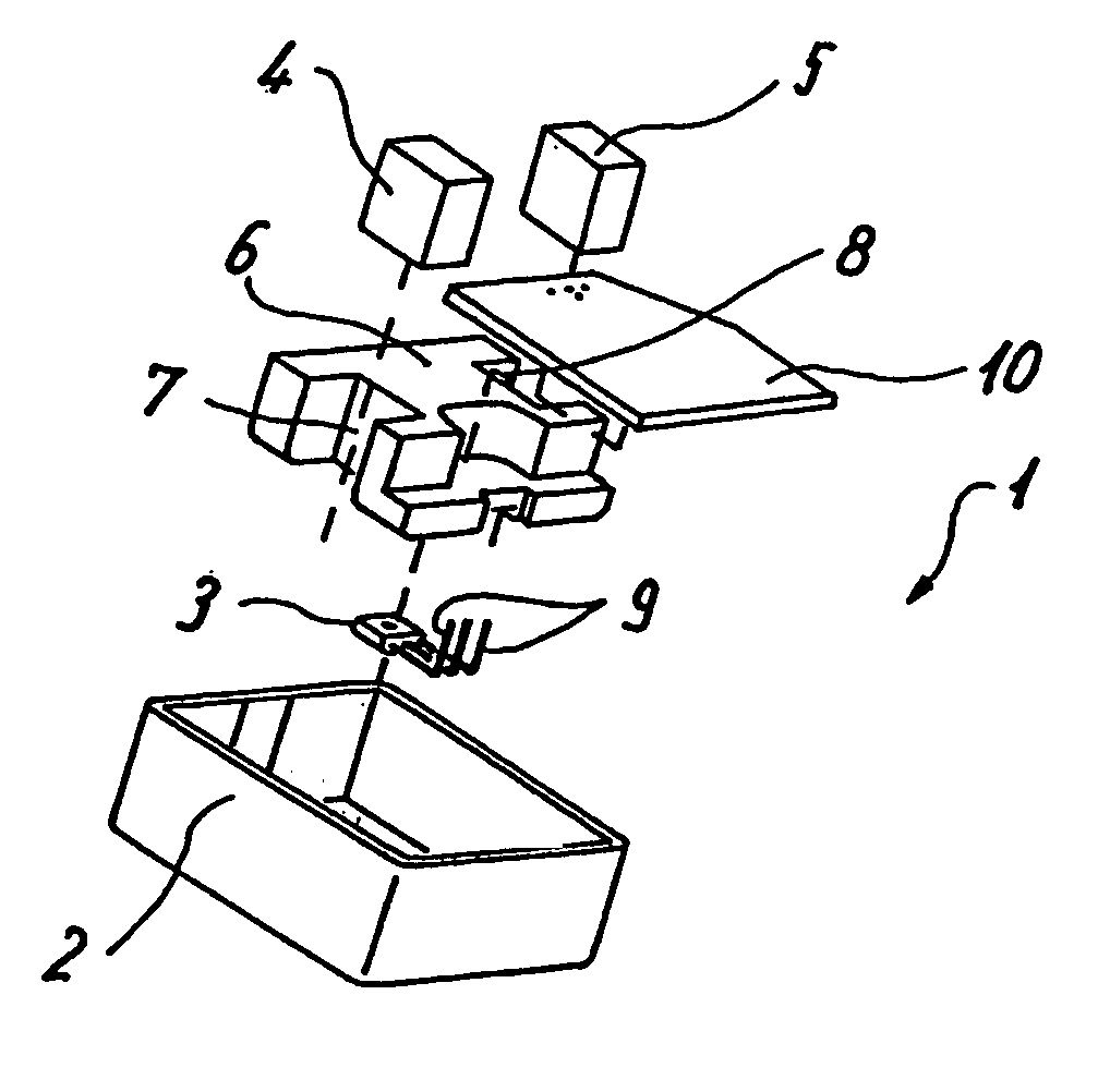
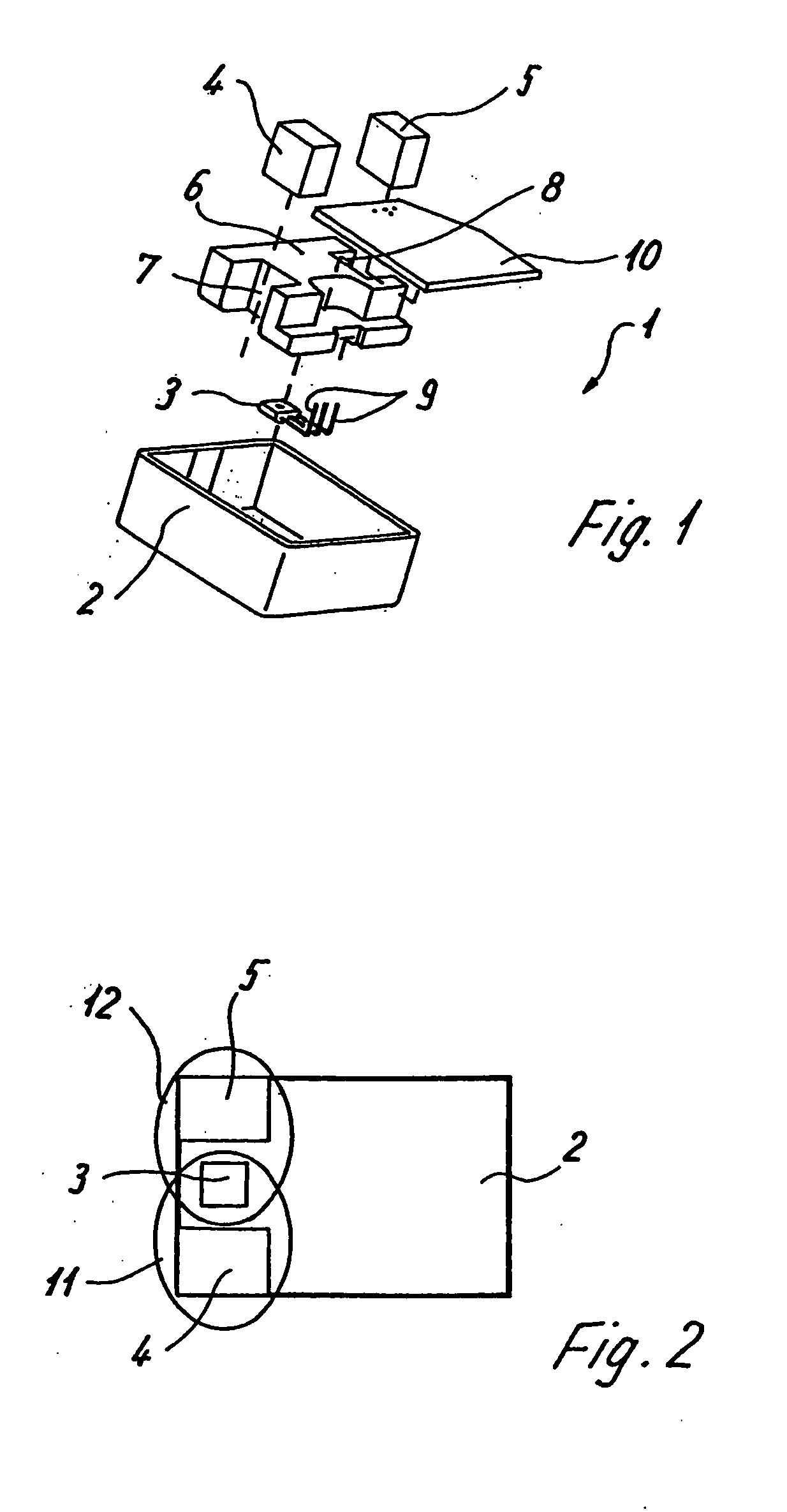
[0018] A sensor system 1 comprises a housing 2, in which a sensor 3 (for example, a Hall sensor) can be mounted. A first magnet 4 and a second magnet 5 are accommodated in the housing 2. The Hall sensor 3 and the magnets 4 and 5 are fixed by a body 6 which has a recess 7 for the magnet 4 and a recess 8 for the magnet 5 as well as a recess on the bottom side for the Hall sensor 3. In this case, the Hall sensor is connected by leads 9 with a printed circuit board 10 on which an electronic analyzing system can be arranged.

[0019] As illustrated in FIG. 2, the Hall sensor 3 is situated between the magnets 4 and 5. In this case, magnet 4 generates a lobar magnetic field 11 which includes the Hall sensor 3. In a similar manner, magnet 5 generates a lobar magnetic field 12 which also includes the Hall sensor 3. In the illustrated sensor system, the magnets 4 and 5 or the magnetic fields 11 and 12 have a symmetrical construction.

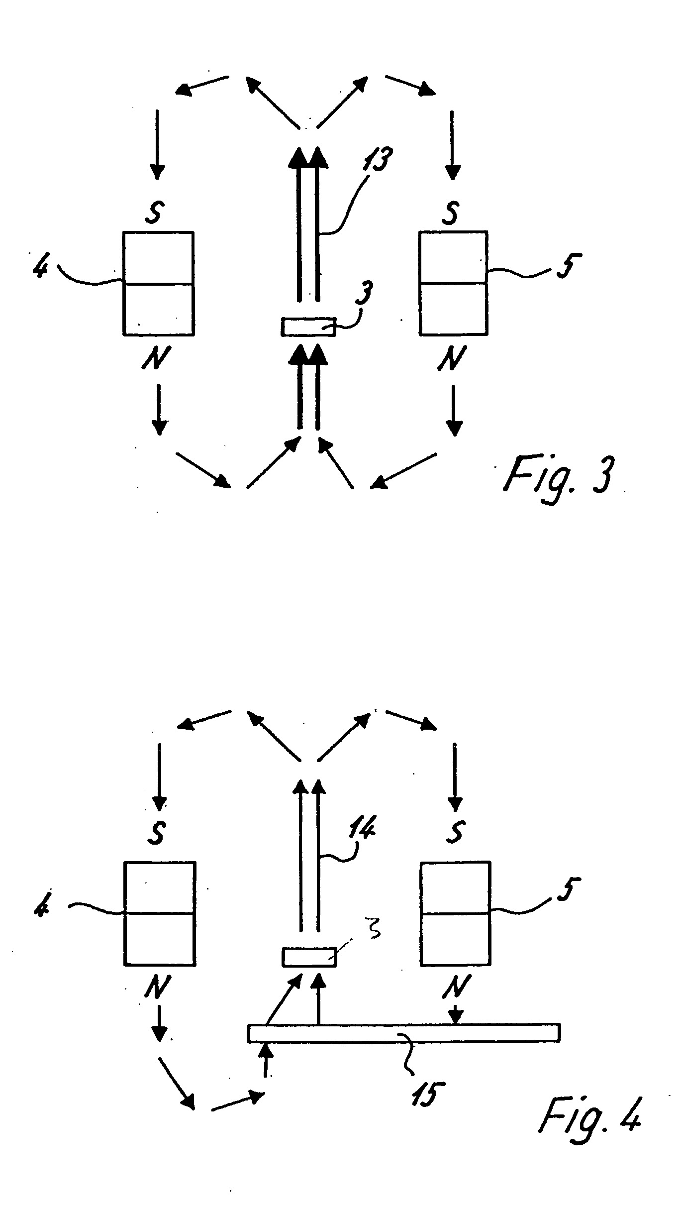
[0020] As illustrated in FIG. 3, the magnets 4 and 5 generate...


PUM


Abstract

A magnetic sensor system, particularly for transport systems, including a ferromagnetic generator which can be moved relative to a magnetic sensor. The magnetic sensor is arranged in the magnetic fields of at least two adjacent magnets in whose magnetic field the generator can be moved. The magnetic fields are constructed as two overlapping lobes, whereby the positioning of the generator can be detected particularly well.

Description

BACKGROUND AND SUMMARY OF THE DISCLOSURE [0001] The present invention relates to a magnetic sensor system, particularly for transport systems, having a ferromagnetic generator, which can be moved relative to a magnetic sensor. [0002] There are sensors which use inductive operating principle to detect electrically conductive materials. As a result of their large adjustable sensitivity, usually large working air gaps can be implemented. However, inductive sensors have the disadvantage that they may be influenced by non-ferromagnetic metallic system parts, such as aluminum. Since, as a result of the arrangement of the signal or ferromagnetic generator, such a sensor should have a wide sensitive track transversely to the moving direction, this leads to a relatively large design. In the case of inductive sensors, the maximal switching frequency depends on the size of the sensor. The minimal demands on the switching frequency are not achieved by an inductive solution. [0003] Additional, c...

Claims


Application Information

Patent Timeline
IPC IPC(8): G01D5/14H01H36/00H03K17/95
CPCH01H36/0026G01D5/147
Inventor WEDEMEYER, TORSTEN
Owner BERNSTEIN AG
Why Eureka
Try Eureka