
Apparatus and method for minimizing influence of temperature change in motor

a technology of minimizing the influence of temperature change and motor, which is applied in the direction of dynamo-electric converter control, dynamo-electric gear control, electric generator control, etc., can solve the problems of rapid deterioration of accelerating ability and fuel economy effect, inability of electric motor to generate desired driving force, etc., to minimize the influence of temperature change of motor

Active Publication Date: 2015-12-10
HYUNDAI MOBIS CO LTD
View PDF7 Cites 6 Cited by
  • Summary
  • Abstract
  • Description
  • Claims
  • Application Information

AI Technical Summary

Benefits of technology

The patent text describes an apparatus and method for controlling a motor to minimize the impact of temperature changes. This is done in real-time to increase efficiency and torque accuracy. The invention uses a single magnetic flux table to reduce processing time and computation load. The technical effects of the invention include improved control and performance of motors in real-time applications.

Problems solved by technology

In this situation, the electric motor cannot generate a desired driving force.
Due to the above, in the electric motor employing the electric motor, an accelerating ability and a fuel economy effect are rapidly deteriorated.
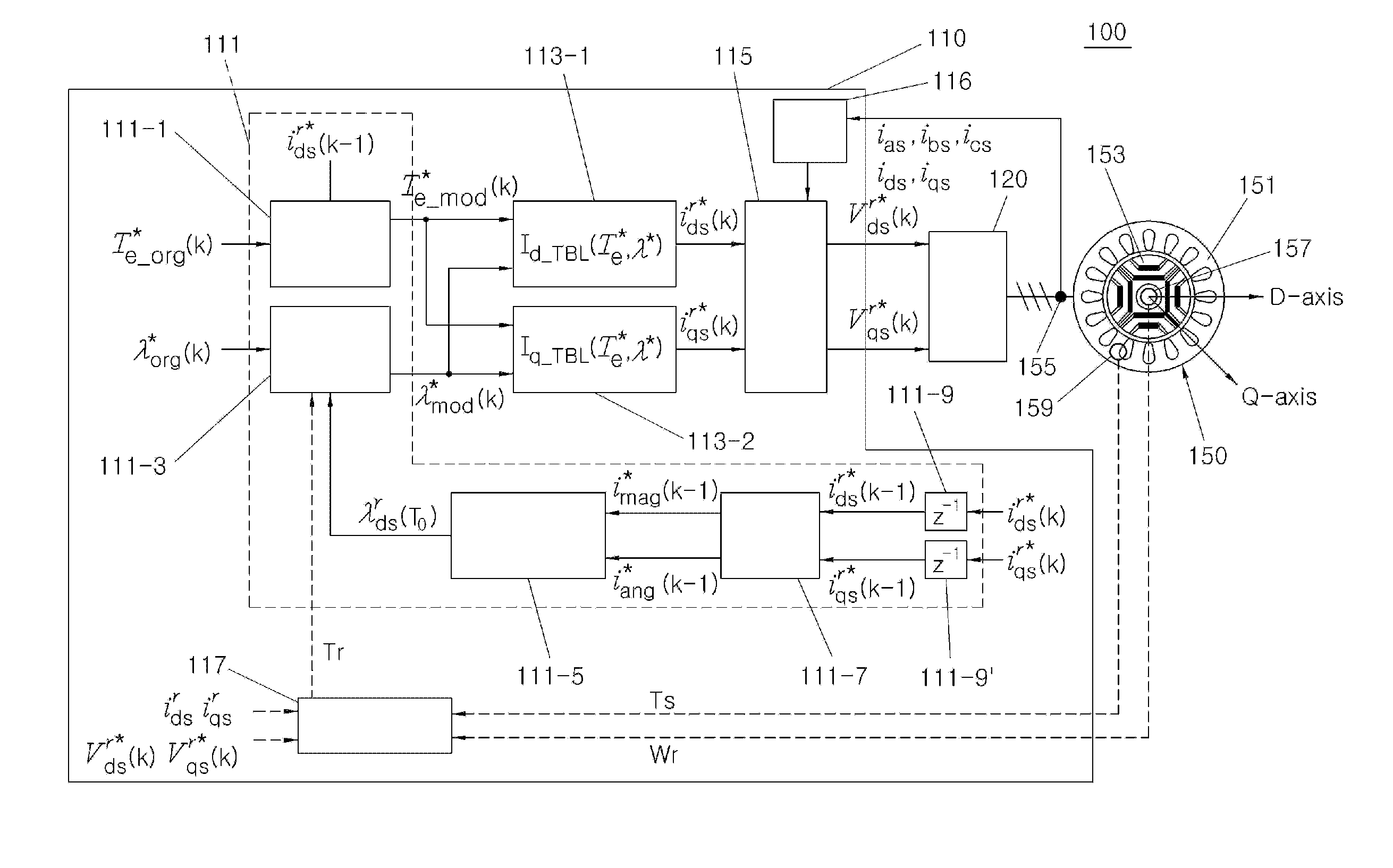
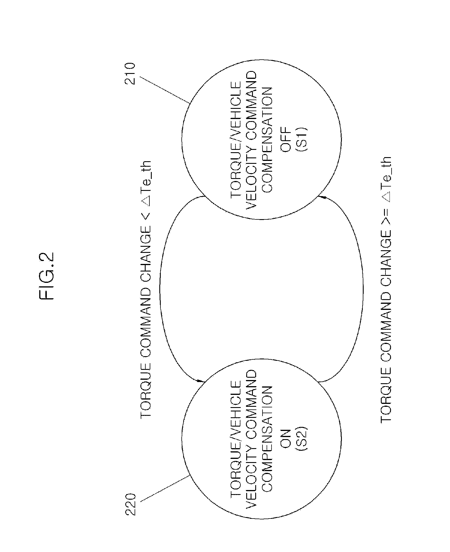
Furthermore, the command compensation unit may perform a compensation if a change of the torque command value is less than a specific value predetermined in advance and may do not perform a compensation if a change of the torque command value is greater than the specific value.

Method used


Image

  • Apparatus and method for minimizing influence of temperature change in motor
  • Apparatus and method for minimizing influence of temperature change in motor
  • Apparatus and method for minimizing influence of temperature change in motor

Examples


Embodiment Construction

[0035]Embodiments are illustrated in the drawings and are described in detail in the present specification. However, it should be understood that the present invention are not limited to specific disclosed embodiments, but include all modifications, equivalents and substitutes encompassed within the spirit and technical scope of the present invention.

[0036]In the drawings, the similar structural components are indicated by the similar reference numerals.

[0037]The terms including the ordinal numeral such as “first”, “second”, etc. may be used to describe various components, but the components are not limited by such terms. The terms are used only for the purpose of distinguishing one component from other components.

[0038]For example, a first component may be designated as a second component without departing from the scope of the present invention. In the same manner, the second component may be designated as the first component. The term “and / or” encompasses both combinations of the...


PUM


Abstract

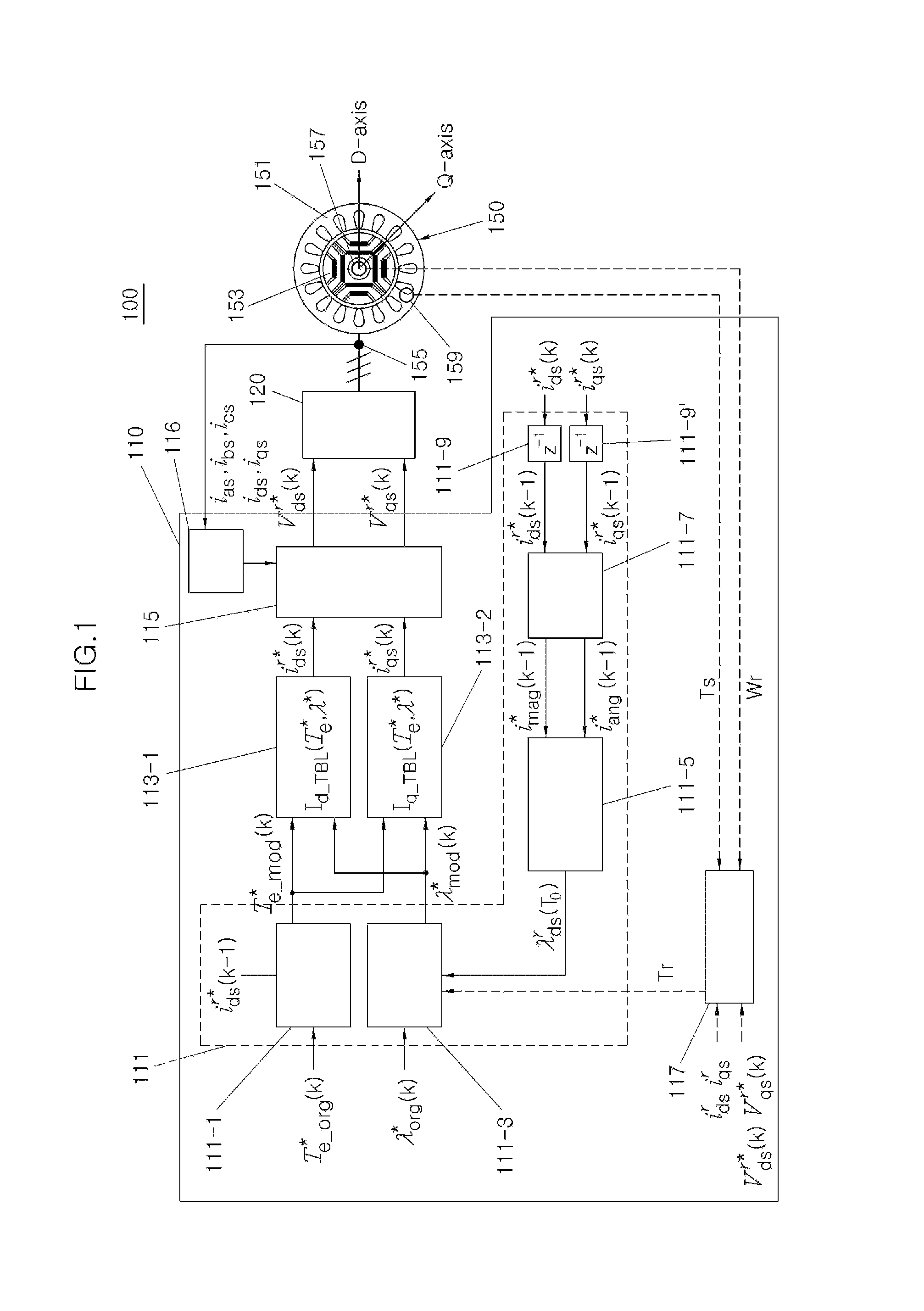
An apparatus for minimizing an influence of a temperature change may include a motor, a temperature sensor for sensing a temperature of the motor to create the temperature information, a command compensation unit compensating a torque command or a magnetic flux demand according to the information on the sensed temperature to create a compensation torque command value or a compensation magnetic flux command value, and an inverter for driving the motor according to a D-axis voltage command value and a Q-axis voltage command value are created according to a D-axis current command value and a Q-axis current command value which are matched with the compensation torque command value or the compensation magnetic flux command value.

Description

CROSS-REFERENCE(S) TO RELATED APPLICATION(S)[0001]This application claims priority to Korean Patent Application No. 10-2014-0069921 filed on Jun. 10, 2014, which is incorporated herein by reference in its entirety.BACKGROUND[0002]1. Field[0003]The present disclosure relates to an apparatus and method for minimizing an influence of a temperature change in a motor.[0004]2. Description of Related Art[0005]In general, to cope with an air pollution and an oil depletion crisis, the technologies related to environmentally friendly vehicles utilizing an electric energy as a power of vehicle have been developed.[0006]A hybrid electric vehicle, a plug-in electric vehicle, a fuel cell electric vehicle and an electric vehicle may be examples of the above environmentally friendly vehicles.[0007]A permanent magnet type electric motor has been widely employed for the above environmentally friendly vehicle. The permanent magnet type electric motor utilizes a permanent magnet to generate a driving f...

Claims


Application Information

Patent Timeline
Patent Type & Authority Applications(United States)
IPC IPC(8): H02P21/14
CPCH02P2021/0064H02P21/141H02P29/60H02P29/66H02P21/22H02P29/662B60L15/2045B60L2240/423B60L2240/425Y02T10/72Y02T10/64Y02T10/70H02P21/14B60L50/50B60W10/08H02P27/06B60L15/20
Inventor KIM, SANG-MIN
Owner HYUNDAI MOBIS CO LTD
Learn More