Atmospheric pollutant granularity based power transmission line path selection method

A technology for atmospheric pollutants and power transmission lines, applied in circuit devices, AC network circuits, electrical components, etc., can solve the problems of reducing the electrical strength of external insulation of power transmission, low accuracy, pollution flashover accidents of high-voltage external insulation equipment, etc. The effect of reducing pollution flashover risk and improving reliability

Active Publication Date: 2017-02-15
ELECTRIC POWER RESEARCH INSTITUTE OF STATE GRID SHANDONG ELECTRIC POWER COMPANY +1
View PDF6 Cites 1 Cited by
  • Summary
  • Abstract
  • Description
  • Claims
  • Application Information

AI Technical Summary

Problems solved by technology

The aggravation of environmental pollution, the deposition of dirt on the surface of high-voltage external insulation equipment, under the action of meteorological conditions such as fog, dew, drizzle, melting ice, and melting snow, reduces the electric strength of the external insulation of power transmission, which may cause the high-voltage external insulation equipment to be in operation. Pollution flashover accidents occur under voltage, which makes the transmission line unable to operate safely and reliably
[0011] Therefore, how to effectively avoid the occurrence of pollution flashover accidents must be considered when selecting transmission line routes to effectively avoid pollution sources or polluted areas. Existing technical means usually use equivalent salt density and gray density to test natural pollution. To characterize the pollution degree of the environment, the method is single and the accuracy is low, and it cannot fully reflect the pollution severity of the line path and the impact on the external insulation of the transmission line

Method used


Image

  • Atmospheric pollutant granularity based power transmission line path selection method

Examples


Embodiment Construction

[0031] The present invention is described in detail below in conjunction with accompanying drawing:

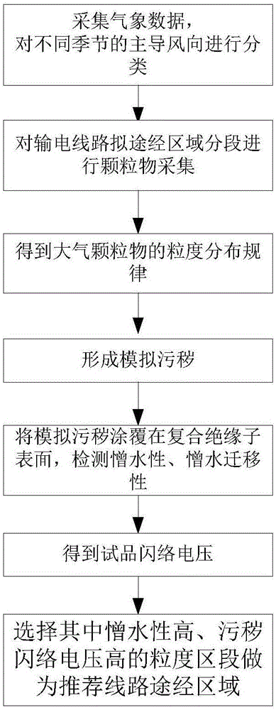
[0032] A transmission line route selection method based on the granularity of atmospheric pollutants, such as figure 1 shown, including the following steps:

[0033] Step 1: Collect the meteorological data of the area where the route is going to pass through, analyze the data, and summarize the dominant wind direction in different seasons; for example, in winter, the dominant wind direction is generally northwest wind. Of course, the specific wind direction is obtained according to statistics, and the dominant wind direction in this season is counted. .

[0034] The collected meteorological data should be more than 10 years old. According to the meteorological data, the dominant wind direction can be classified according to the number of months the wind direction lasts.

[0035] Step 2: Under different prevailing wind directions, use the atmospheric particulate matter collec...


PUM


Abstract

The invention discloses an atmospheric pollutant granularity based power transmission line path selection method, which comprises the steps of acquiring meteorological data of a region by which a power transmission line is planned to pass, and classifying dominant wind directions in different seasons; performing particulate matter collection on the region by which the power transmission line is planned to pass in a segmentation manner; performing granularity analysis on particulate matters in different segments under different dominant wind directions; coating a fixed amount of simulated dirty on a certain area of the surface f a composite insulator, and detecting the hydrophobicity and hydrophobic mobility; performing a flashover test on a test object to acquire flashover voltage; and selecting the granularity with high hydrophobicity and high dirty flashover voltage, and regarding a segment with the granularity to be a recommended path passing region. The power transmission line path selection method has the beneficial effects that the pollution severity of a line path can be evaluated comprehensively, the risk of pollution flashover is reduced, and the line running reliability is improved.

Description

technical field [0001] The invention belongs to the technical field of power transmission line route selection, and in particular relates to a power transmission line route selection method based on the granularity of air pollutants. Background technique [0002] Path selection and survey are the key points in the design of the entire transmission line, and the rationality of the scheme plays an important role in the economic, technical indicators, construction and operating conditions of the line. It is necessary to reasonably shorten the path length and reduce line investment, but also to ensure that the line is safe, reliable, and easy to operate. [0003] Air pollutants refer to those substances that are discharged into the atmosphere due to human activities or natural processes and have harmful effects on the environment or people. The combustion process of fuel (coal, oil, natural gas, etc.) is an important source of pollutants delivered to the atmosphere. The compos...

Claims


Application Information

Patent Timeline
Patent Type & Authority Applications(China)
IPC IPC(8): H02J3/00G06Q50/06G06Q10/04
CPCG06Q10/047G06Q50/06H02J3/00H02J2203/20
Inventor 刘辉沈庆河苏建军雍军刘嵘张洋姚金霞杨波孙晓斌黄振宁漆照段玉兵张皓张思远
Owner ELECTRIC POWER RESEARCH INSTITUTE OF STATE GRID SHANDONG ELECTRIC POWER COMPANY
Why Eureka
Try Eureka