Reference signal mapping method and device
A technology of reference signal and mapping method, which is applied in the directions of pilot signal allocation, separation device of transmission path, wireless communication, etc., and can solve problems such as inability to support CSI-RS
- Summary
- Abstract
- Description
- Claims
- Application Information
AI Technical Summary
Problems solved by technology
Method used
Image
Examples
Embodiment 1
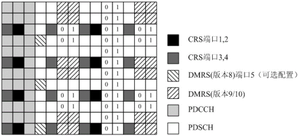
[0061] Embodiment 1 describes a scheme of obtaining a 12-port signal reference pattern according to a 4-port reference signal pattern and an 8-port reference signal pattern.
[0062] Figure 3a A 12-port reference signal pattern is shown. It should be noted, Figure 3a Only one possible 12-port reference signal pattern is shown, and other 12-port reference signal patterns can also be obtained based on the distribution law of the aforementioned 12-port reference signal patterns, which will not be listed here.
[0063] Figure 3a In , for convenience of description, each grid represents one RE, and the position of one RE can be represented by coordinates (x, y), where x represents a symbol number, and y represents a subcarrier number. The numerical value in each square indicates the port number.
[0064] Such as Figure 3a As shown in the figure, three groups of 12-port CSI-RS patterns are shown in the figure, where:
[0065] The REs to which the first group of CSI-RSs are...
Embodiment 2
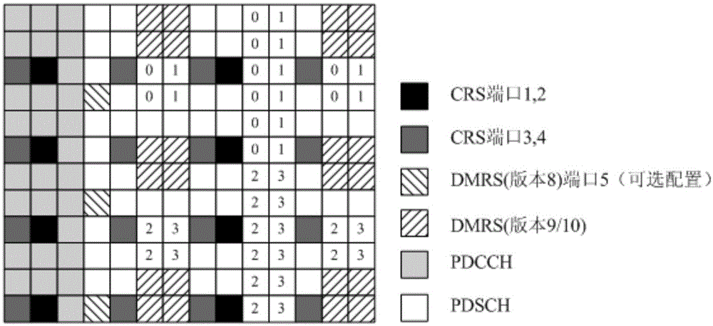
[0082] Embodiment 2 describes a scheme of obtaining a 12-port reference signal pattern according to an 8-port reference signal pattern.
[0083] Figure 4a A 12-port reference signal pattern is shown. It should be noted, Figure 4a Only one possible 12-port reference signal pattern is shown, and other 12-port reference signal patterns can also be obtained based on the distribution rules of the 12-port reference signal patterns described in the foregoing embodiments, which will not be listed here.
[0084] Figure 4a In , for convenience of description, each grid represents one RE, and the position of one RE can be represented by coordinates (x, y), where x represents a symbol number, and y represents a subcarrier number. The numerical value in each square indicates the port number.
[0085] Such as Figure 4a As shown, the figure shows four groups of 12-port CSI-RS patterns, wherein the patterns of the first group of CSI-RS and the second group of CSI-RS conform to the la...
Embodiment 3
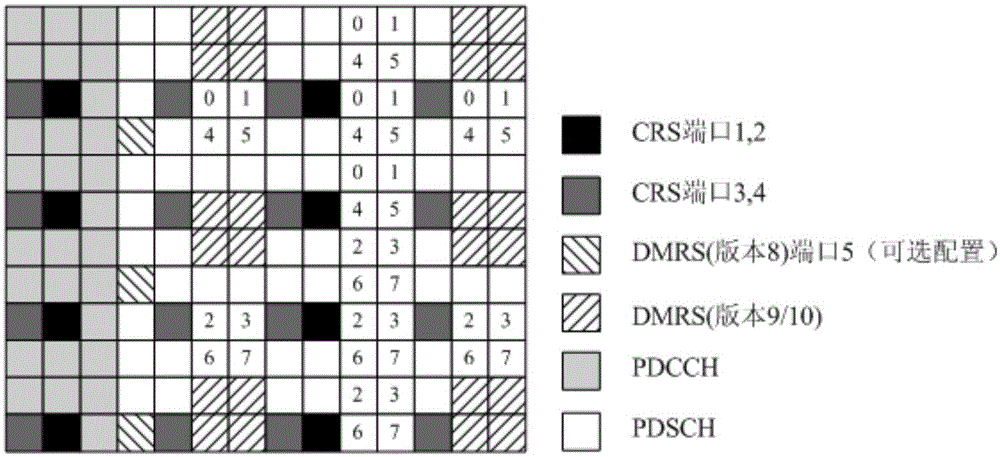
[0103] Embodiment 3 describes another solution for obtaining a 12-port reference signal pattern according to an 8-port reference signal pattern.
[0104] Figure 5a A 12-port reference signal pattern is shown. It should be noted, Figure 5a Only one possible 12-port reference signal pattern is shown, and other 12-port reference signal patterns can also be obtained based on the distribution law of the aforementioned 12-port reference signal patterns, which will not be listed here.
[0105] Figure 5a In , for convenience of description, each grid represents one RE, and the position of one RE can be represented by coordinates (x, y), where x represents a symbol number, and y represents a subcarrier number. The numerical value in each square indicates the port number.
[0106] Such as Figure 5a As shown, the figure shows four groups of 12-port CSI-RS patterns, and these four groups of CSI-RS can be distributed according to the sixth distribution in the aforementioned 12-por...
PUM
 Abstract
Description
Claims
Application Information
 - R&D
- Intellectual Property
- Life Sciences
- Materials
- Tech Scout
- Unparalleled Data Quality
- Higher Quality Content
- 60% Fewer Hallucinations
Browse by: Latest US Patents, China's latest patents, Technical Efficacy Thesaurus, Application Domain, Technology Topic, Popular Technical Reports.
© 2025 PatSnap. All rights reserved.Legal|Privacy policy|Modern Slavery Act Transparency Statement|Sitemap|About US| Contact US: help@patsnap.com


