
Hydraulic pump installation structure

A mounting structure, hydraulic pump technology, applied to parts, pump elements, transmissions, etc. of pumping devices used for elastic fluids, can solve the problem of not being able to fully suppress the displacement of the pump casing, not being easy to set the thickness of the supporting member, Shape and other problems, to achieve the effect of suppressing displacement, suppressing the number of parts, and suppressing relative displacement

Active Publication Date: 2018-09-07
HONDA MOTOR CO LTD
View PDF6 Cites 0 Cited by
  • Summary
  • Abstract
  • Description
  • Claims
  • Application Information

AI Technical Summary

Problems solved by technology

Therefore, it is not easy to set the plate thickness and shape of the support
Also, in the case where the hydraulic reaction force acting on the pump casing is large, the displacement of the pump casing may not be sufficiently suppressed only by the above-mentioned support.

Method used


Image

  • Hydraulic pump installation structure
  • Hydraulic pump installation structure
  • Hydraulic pump installation structure

Examples


Embodiment Construction

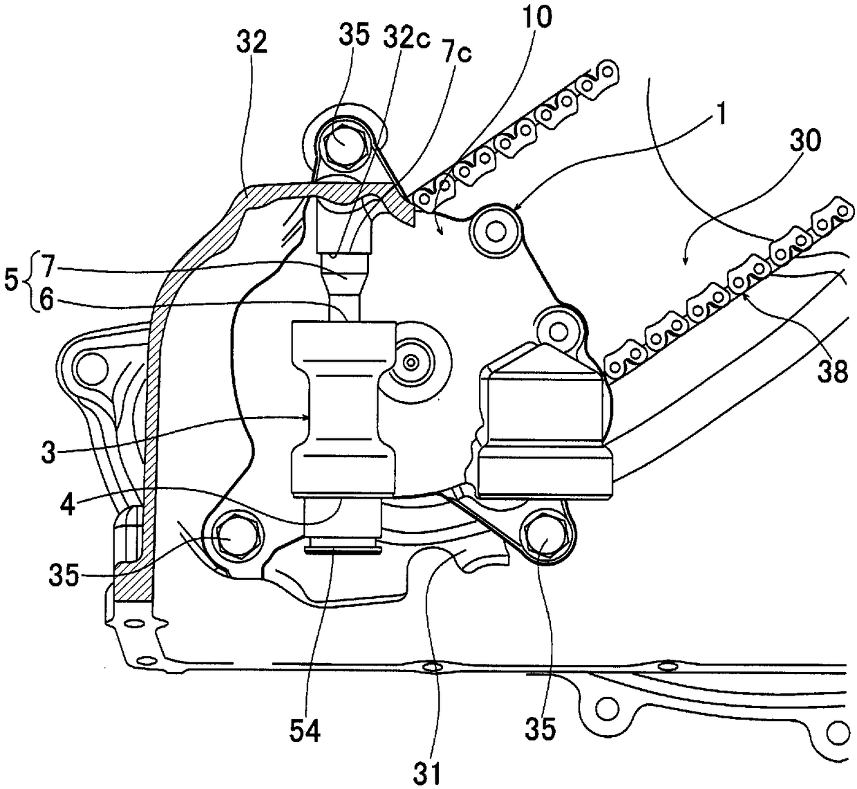
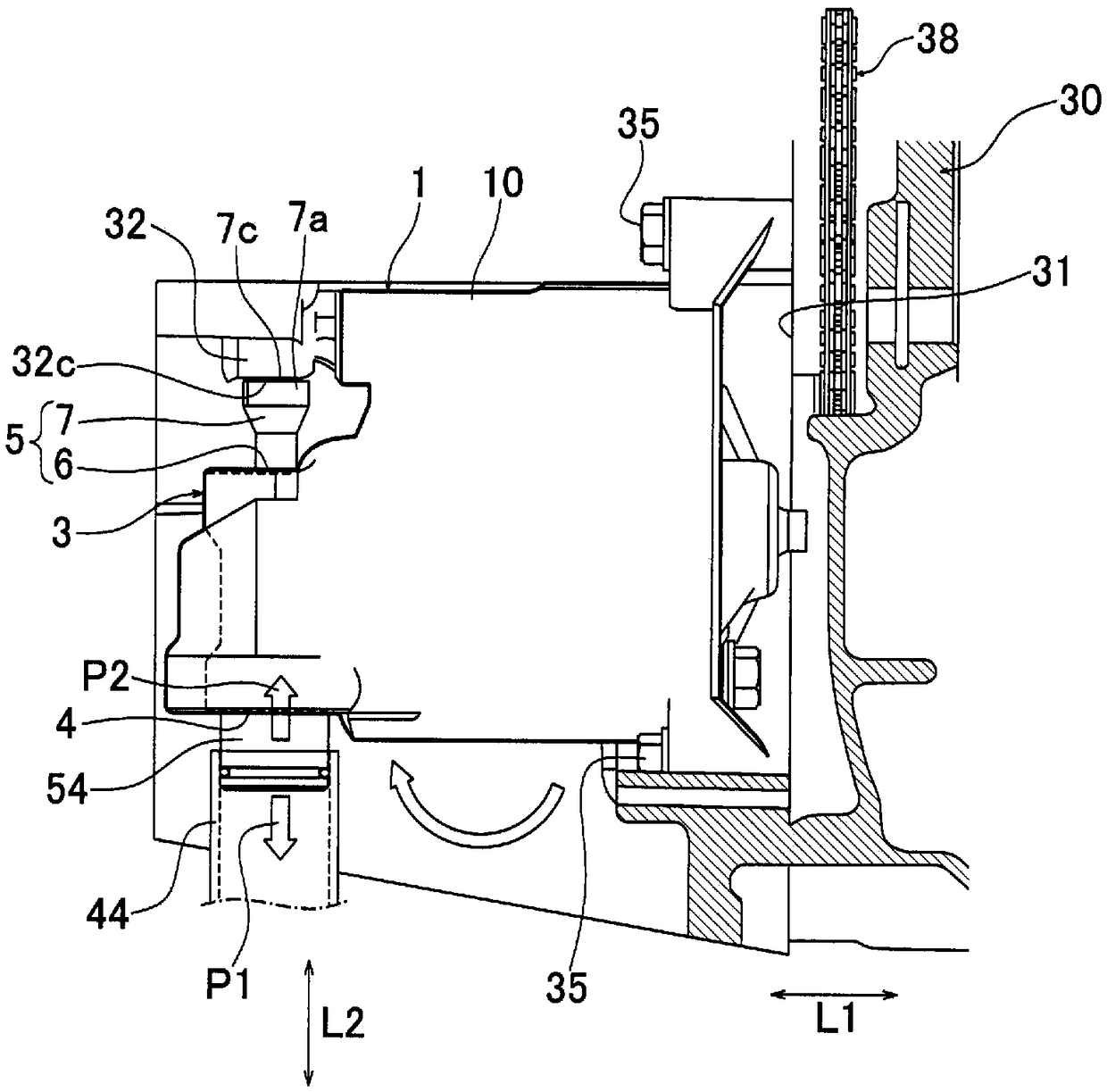
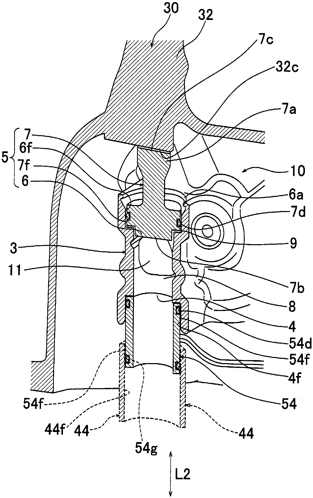
[0023] Hereinafter, embodiments of the present invention will be described in detail with reference to the drawings. figure 1 and figure 2 It is a figure which shows the hydraulic pump 1 mounted|worn in the mounting structure of one embodiment of this invention, figure 1 is the main view, figure 2 is a side view. and, image 3 It is a perspective view showing a part of the pump housing 10 of the hydraulic pump 1 and the transmission housing 30 of the transmission in cross section.

[0024] The mounting structure of the hydraulic pump 1 in the present embodiment is a mounting structure of the hydraulic pump 1 for supplying hydraulic pressure to a hydraulic control device (control body) included in a transmission (the overall illustration is omitted). Such as figure 1 and figure 2 As shown, the installation structure has: a substantially planar installation surface 31, which is used to install the hydraulic pump 1 on the transmission case 30; the pump housing 10 of the ...


PUM


Abstract

Provided is a hydraulic pump mounting structure configured so that, with the use of a simple structure having a reduced number of parts, the hydraulic pump mounting structure can effectively reduce the displacement of a hydraulic pump caused by the discharge pressure of hydraulic oil. A hydraulic pump mounting structure comprises: a mounting surface (31) for a hydraulic pump (1), the mounting surface (31) being provided on a transmission casing (30); a pump casing (10) for the hydraulic pump (1) mounted on the mounting surface (31); the discharge port (3) of the hydraulic pump (1), the discharge port (3) being formed protruding from the pump casing (10) and being disposed on a surface different from the mounting surface (31); a discharge opening (4) provided at the discharge port (3) and discharging hydraulic oil; a hydraulic pressure-subjected section (5) provided to the discharge port (3) and subjected to the pressure of hydraulic oil discharged from the discharge opening (4), the pressure acting in the direction opposite the direction toward the discharge opening (4) with both directions lying along the same axis; and a contact section (7c) provided to the hydraulic pressure-subjected section (5) and disposed so as to be capable of coming into contact with the contact receiving section (32c) of the transmission casing (30).

Description

technical field [0001] The present invention relates to a mounting structure of a hydraulic pump for supplying hydraulic pressure to a device having a mechanism that operates using hydraulic pressure of working oil. Background technique [0002] In a vehicle automatic transmission (automatic transmission) that has a hydraulic control device (hydraulic control body) and requires high hydraulic pressure, for example, as shown in Patent Document 1, when there is supply of hydraulic oil from a hydraulic pump (hydraulic pump) to the hydraulic control device, the In the case of conveying pipes such as connecting pipes. In such a structure, the discharge port of the hydraulic pump may be deformed and displaced due to the hydraulic reaction force, and sealing members such as an O-ring connected to the delivery pipe may be abnormally worn. In particular, in a structure in which the hydraulic pump discharges hydraulic oil in a direction perpendicular to the tightening direction of th...

Claims


Application Information

Patent Timeline
Patent Type & Authority Patents(China)
IPC IPC(8): F04B53/00F16H3/00
CPCF04B53/00F16H3/00
Inventor 高田雄一郎
Owner HONDA MOTOR CO LTD
Learn More