Oil distribution element

A hollow, rotor shaft technology, used in electrical components, electric components, electromechanical devices, etc., can solve problems such as too small cross-section of pipelines, increase in moving mass, and reduce volume requirements, and achieve increased weight per unit power, large output, Efficient cooling effect

Active Publication Date: 2017-02-15
THYSSENKRUPP PRESTA TECCENTER AG
View PDF5 Cites 6 Cited by
  • Summary
  • Abstract
  • Description
  • Claims
  • Application Information

AI Technical Summary

Problems solved by technology

However, it has been found to be impractical to remove sufficient heat by conduction in this way
[0005] Finally, all known cooling devices have one of the disadvantages of choosing too small a cross-section of the lines provided for the coolant, thereby reducing volume requirements
A disadvantage in this case, however, is that the hollow cylinder must be almost completely filled with coolant during operation, which increases the coolant requirement and thus leads to an increased moving mass, which is especially desirable in lightweight construction Avoided

Method used


Image

  • Oil distribution element
  • Oil distribution element

Examples


Embodiment Construction

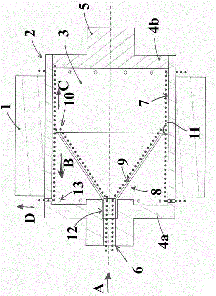
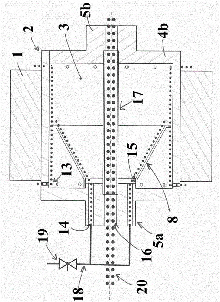
[0029] exist figure 1 , firstly shows a rotor for an electric machine, in particular for an asynchronous or permanent magnet synchronous machine, which has a hollow rotor shaft equipped with a laminated core 1 . The hollow rotor shaft is formed by a cylindrical barrel 2 which surrounds a shaft cavity 3 and is closed on both sides by surface flanges 4 . In this example, one surface flange 4 a is formed on the cylindrical barrel 2 and the other flat flange 4 b is fitted into the cylindrical barrel 2 . In each case, at both surface flanges 4 there is provided a journal 5 which is formed on or attached as a separate component. In one of the journals 5 there is provided an inlet 6 through which a cooling fluid (shown as a dot) enters the shaft chamber 3 in the direction of arrow A and reaches the inner surface 7 of the cylindrical barrel.

[0030] In the shaft cavity 3 is arranged a distribution element 8 which receives the cooling fluid entering through the inlet 6 and passes th...


PUM


Abstract

The invention relates to a hollow rotor shaft for the rotor of an electric motor, comprising a cylindrical casing which is closed at both ends by end flanges and surrounds a shaft cavity, wherein a shaft journal is formed on each of the end flanges and wherein in one of the shaft journals an inlet is provided, through which a cooling liquid enters the shaft cavity and reaches the inner surface of the cylinder, said rotor shaft also comprising a distribution element which is disposed in the shaft cavity and receives the cooling liquid entering via the inlet, guides said liquid over a rotationally symmetrical diverting surface in the direction of the inner surface of the cylindrical casing, and passes said liquid via a mouth region onto the inner surface.

Description

technical field [0001] The invention relates to a hollow rotor shaft for the rotor of an electric machine, which has a cylindrical shell closed on both sides by surface flanges (Stirnflansche), which encloses a hollow shaft space, wherein in each case A journal is positioned at each of the surface flanges, and wherein an inlet is provided in one of the surface flanges, in particular in the journal, through which a cooling fluid enters the hollow shaft space and reaches the inner surface of the cylindrical barrel. Background technique [0002] Various rotors are known from the prior art for electric machines on which metal laminations are arranged, which are usually combined in groups. Such rotors are used, for example, in asynchronous machines and in permanent-magnet synchronous machines. All electric motors heat up significantly during operation due to electromagnetic activity in the rotor and the resulting heat transfer to other weight-optimized support components. Diffe...

Claims


Application Information

Patent Timeline
Patent Type & Authority Applications(China)
IPC IPC(8): H02K7/00H02K9/193
CPCH02K7/003H02K9/193H02K9/19H02K9/10
Inventor 丹尼尔·保罗克里斯蒂安·奎绍
Owner THYSSENKRUPP PRESTA TECCENTER AG
Why Eureka
Try Eureka