Light transfer apparatus and light transfer method

A technology of optical transmission and optical signal, applied in the direction of optical fiber transmission, transmission system, electromagnetic wave transmission system, etc., can solve problems such as large circuit scale

Active Publication Date: 2017-02-15
MITSUBISHI ELECTRIC CORP
View PDF5 Cites 2 Cited by
  • Summary
  • Abstract
  • Description
  • Claims
  • Application Information

AI Technical Summary

Problems solved by technology

[0009] However, in the method for compensating the nonlinear optical effect described above, there are problems in that the scale of the circuit

Method used


Image

  • Light transfer apparatus and light transfer method
  • Light transfer apparatus and light transfer method
  • Light transfer apparatus and light transfer method

Examples


Embodiment approach 1

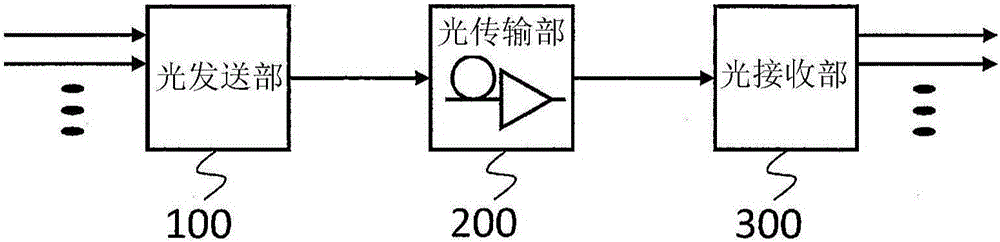
[0039] figure 1 It is a block diagram showing the configuration of the optical transmission device according to Embodiment 1 of the present invention. exist figure 1 An example of an optical transmission system using the optical transmission method according to Embodiment 1 of the present invention is shown in . exist figure 1 Among them, the optical transmission device includes an optical transmission unit 100 , an optical transmission unit 200 , and an optical reception unit 300 .

[0040] The optical transmission unit 100 transmits an optical signal, the optical transmission unit 200 is composed of an optical fiber and transmits the optical signal, and the optical reception unit 300 receives the optical signal. Furthermore, the optical transmission device according to Embodiment 1 of the present invention includes at least one of the light transmitting unit 100 and the light receiving unit 300 .

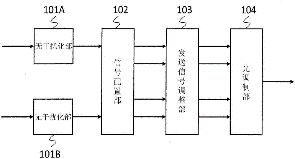
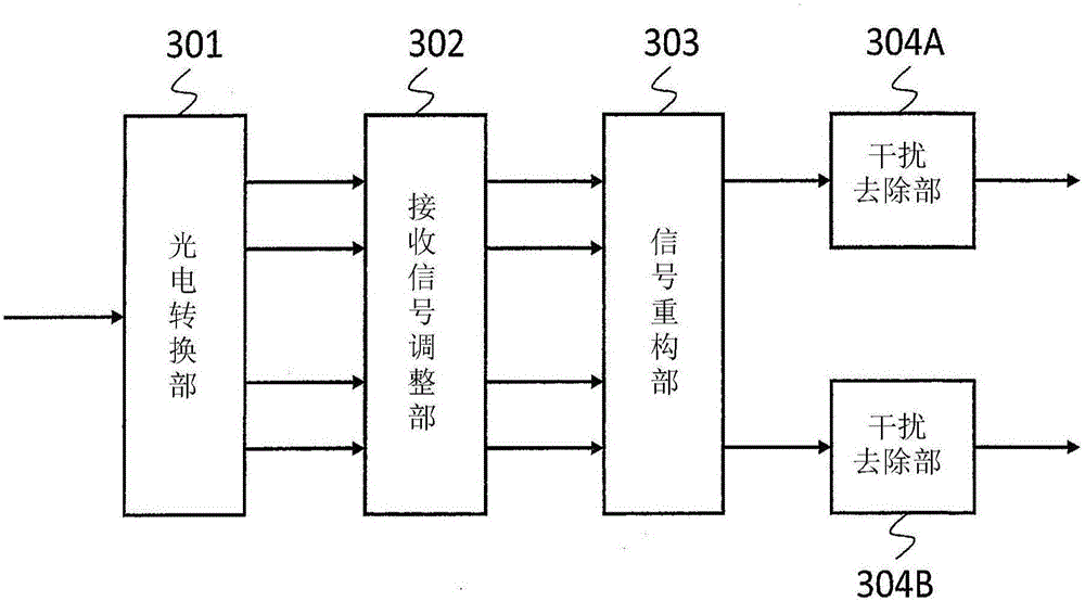
[0041] figure 2 is shown in detail figure 1 A structural block diagram...


PUM


Abstract

This invention provides a light transfer apparatus and a light transfer method wherein a pair of phase conjugation signals can be transferred without degradation of frequency utilization efficiency and combined on a reception side with the transfer quality degradation being suppressed. The light transfer apparatus connects the light transmission unit (100) and the light reception unit (300) through the light transfer unit (200). The light transmission unit (100) comprises: a signal arrangement unit (102) that generates, on the basis of externally input plural-system signals, a pair of plural-system phase conjugation signals and mixture-dispersion-arranges the pair of phase conjugation signals in an orthogonal polarization electric-field; and a light modulation unit (104) that converts the electric signals supplied from the signal arrangement unit (102) into a light signal and outputs the light signal to the light transfer unit (200). The light reception unit (300) comprises: a photoelectric conversion unit (301) that converts the light signal transferred by the light transfer unit (200) into the electric signals; and a signal reconstruction unit (303) that combines the mixture-dispersion-arranged signals supplied from the photoelectric conversion unit (301), thereby reconstructing the original plural-system signals.

Description

technical field [0001] The present invention relates to an optical transmission device and an optical transmission method using a digital coherent method. Background technique [0002] In order to enable long-distance and large-capacity optical transmission, the subject is to overcome the limit of the optical signal-to-noise power ratio, realize high-density wavelength multiplexing, and overcome the nonlinear optical effect of optical fibers. [0003] First, on-off keying (OOK: On-Off Keying) is currently used as a technique for overcoming the limit of the optical signal-to-noise power ratio. However, in recent years, binary phase shift modulation (BPSK: Binary Phase-Shift Keying) or quaternary PSK (QPSK: Quaternary Phase-Shift Keying) has been adopted. [0004] Next, as a technique for realizing high-density wavelength multiplexing, a method of doubling the number of transmission bits per symbol by employing a polarization multiplexing method (Polarization Multiplexing) is...

Claims


Application Information

Patent Timeline
IPC IPC(8): H04B10/556G02F1/01H04J14/00H04J14/04H04J14/06
CPCH04B10/556H04B10/532H04B10/2507H04B10/40H04B10/58H04B10/616
Inventor 吉田刚
Owner MITSUBISHI ELECTRIC CORP
Why Eureka
Try Eureka