Mobile automatic fixed-point fertilizer applicator
A fertilizer applicator and mobile technology, applied in the field of mobile automatic fixed-point fertilizer applicators, can solve the problems of cumbersome operation, low work efficiency, small floor space, etc., and achieve simple and convenient operation, high fertilizer efficiency, and small floor space. Effect
- Summary
- Abstract
- Description
- Claims
- Application Information
AI Technical Summary
Problems solved by technology
Method used
Image

Examples
Embodiment 1
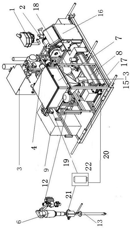
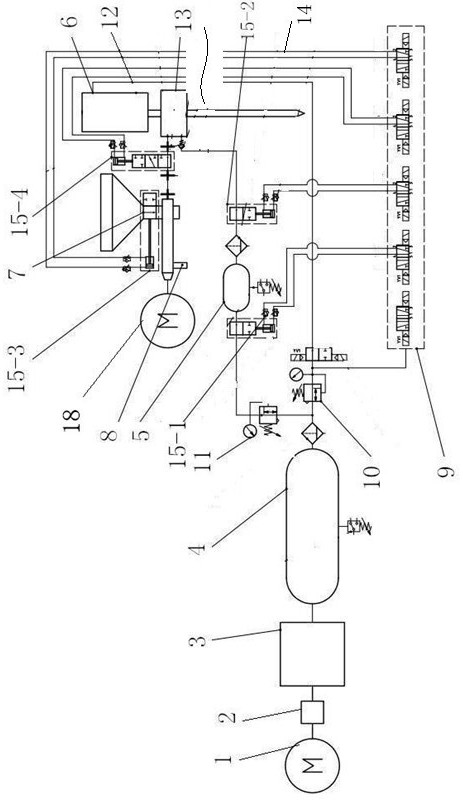
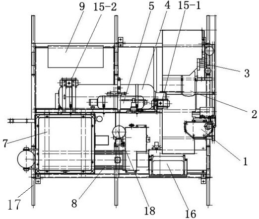
[0025] Example 1: as figure 1 , 2 A mobile automatic fixed-point fertilizer spreader shown in and 3, the fixed-point fertilizer spreader includes: a power system, a feeding transmission system, a pressure system, a control system and a starting hammer. The power system includes an engine 1, an air compressor 3, a transmission wheel 2 and a transmission motor 18; the feeding transmission system includes a feeding funnel 7, a screw extrusion groove 8 and a material transmission pipe 20; the pressure system includes a constant pressure pressure vessel 4, a regulating Pressure vessel 5, pressure control pipeline 14, air pressure transmission pipe 19, low pressure control valve 10, air pressure shut-off valve 15 and connecting pipeline; control system includes distribution box 9 and operation panel 16; starting hammer includes impact pneumatic hammer 6 , drilling needle 13 and switching valve 22 .
Embodiment 2
[0026] Example 2: as figure 1 , 2 As shown in and 3, the engine 1 is connected to the air compressor 3 through the transmission wheel 2 and the transmission belt, and the air compressor 3 is connected to the constant pressure pressure vessel 4 through the pipeline, and the constant pressure pressure vessel 4 There are two branch pipelines, one branch pipeline is connected to the pressure regulating pressure vessel 5 through the pressure conversion valve 11, and the other branch pipeline is connected to the low pressure control valve 10, and the low pressure control valve 10 is connected to a pressure The control pipeline 14 and the low pressure transmission pipe 12, the pressure control pipeline 14 is connected to the air pressure shut-off valve 15, the low pressure transmission pipe 12 is connected to the impact type pneumatic hammer 6, and the pressure regulating pressure vessel 5 is connected to the air pressure transmission pipe 19. The air pressure transmission pipe 19 i...
Embodiment 3
[0027] Example 3: as figure 1 , 2As shown in and 3, the air compressor 3 of the present invention provides pressure inside the constant pressure pressure vessel 4, the pressure in the constant pressure pressure vessel 4 is generally 280-300Pa, and the pressure in the pressure regulating pressure vessel 5 is generally 150-160Pa , while the control pressure of the air pressure cut-off valve 15 is 6-7Pa, the working pressure of the impact-type pneumatic hammer 6 is 6-7Pa, and the compressed air in the constant-pressure pressure vessel 4 is converted by the low-pressure control valve 10, and part of it is used as power to supply the impact-type The pneumatic hammer 6 and the rest are used as the control air pressure of the air pressure cut-off valve 14. Since the required pressure of the two is the same, the air pressure in the constant pressure pressure vessel 4 is directly used for conversion; The working pressure requires a large working pressure. During the working process, t...
PUM
 Abstract
Description
Claims
Application Information