
Die seat for punching machine

A die base and punching machine technology, which is applied to forming tools, manufacturing tools, metal processing equipment, etc., can solve the problem that the cooling strength is difficult to meet the stamping requirements of large-tonnage workpieces, and achieve the effect of meeting the stamping requirements and improving the cooling strength.

Active Publication Date: 2018-12-04
安徽中瑞机床制造有限公司
View PDF6 Cites 0 Cited by
  • Summary
  • Abstract
  • Description
  • Claims
  • Application Information

AI Technical Summary

Problems solved by technology

[0007] The purpose of the present invention is to overcome the deficiency that the cooling strength of the existing stamping dies is gradually difficult to meet the stamping requirements of large-tonnage workpieces, and to provide a mold base for stamping machines with significantly improved cooling strength

Method used


Image

  • Die seat for punching machine
  • Die seat for punching machine
  • Die seat for punching machine

Examples


Embodiment 1

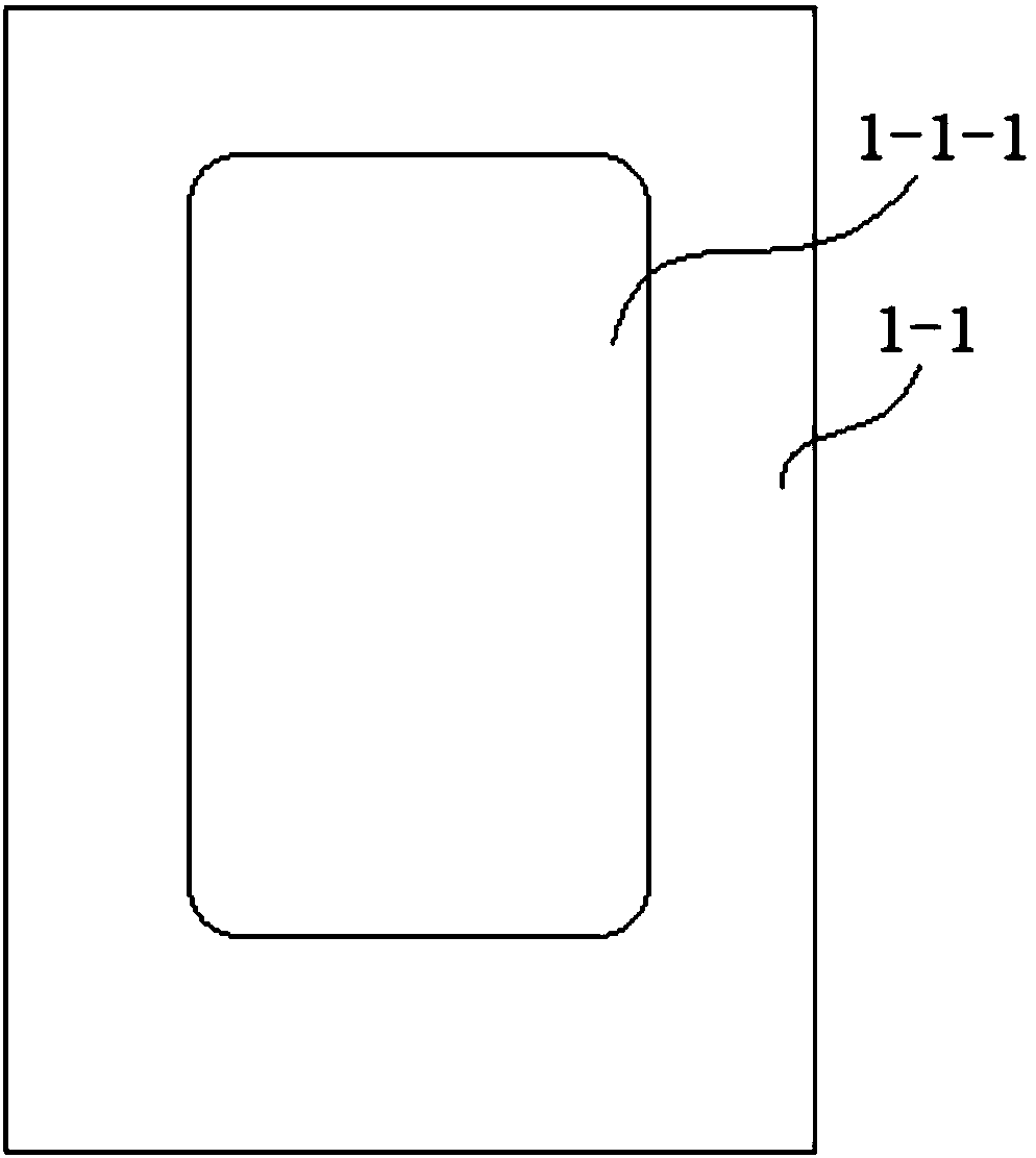
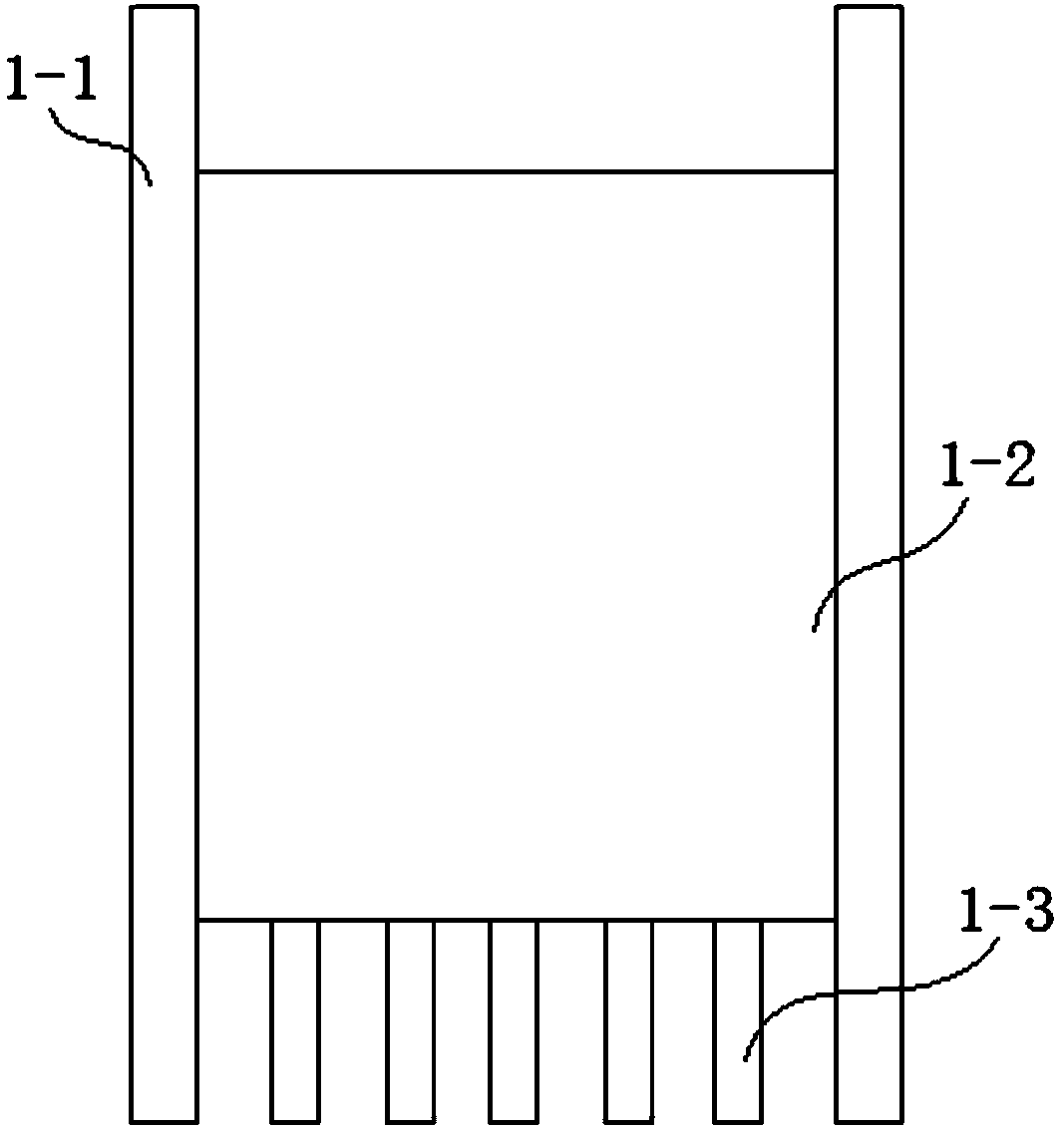
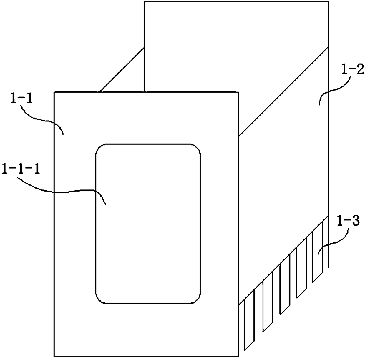
[0041] refer to Figure 1-9 , an integral hydraulic punching machine in this embodiment, comprising a main frame, the main frame includes two vertical plates 1-1 placed longitudinally on the front and rear sides of the two vertical plates 1-1, and the left and right sides of the two vertical plates 1-1 pass through the corresponding The side connection plate 1-2 is connected; the bottom end of the side connection plate 1-2 is connected with several parallel bottom reinforcement plates 1-3; the vertical plate 1-1 is provided with a vertical plate through hole 1-1-1, the The through hole 1-1-1 of the vertical plate is a rectangular through hole, and the four corners of the rectangular through hole are rounded;

[0042]In this embodiment, the main frame with the above-mentioned structure can significantly reduce the consumption of steel on the premise of ensuring the good strength, rigidity and vibration resistance of the fuselage itself, especially for working conditions that re...

Embodiment 2

[0062] refer to Figure 10 , an assembly method of the integral hydraulic stamping machine as described in embodiment 1, comprising the following steps:

[0063] Step 1, set up hoisting holes on the four corners of the vertical plate 1-1 respectively, so as to facilitate the hoisting of the vertical plate 1-1;

[0064] Step 2. First, place the two vertical boards 1-1 horizontally, and then adjust the distance between the two vertical boards 1-1 to the specified value. Because the vertical boards 1-1 are high and difficult to locate , in this embodiment, the two vertical plates 1-1 are laid down horizontally, which reduces the difficulty of processing;

[0065] Step 3: Correspondingly connect the four corners of the two vertical plates 1-1 through the four positioning connecting columns. In this embodiment, first determine the distance between the two vertical plates 1-1 through the four positioning connecting columns, and then Subsequent processing is carried out to avoid th...


PUM


Abstract

The invention discloses a die base for a stamping machine and belongs to the field of stamping devices. The die base for the stamping machine comprises an upper die base and a lower die base, wherein a cooling mechanism is installed on the upper die base or the lower die base. The cooling mechanism comprises a moving platform, a containing cavity and an ejection device, wherein the moving platform is embedded into the containing cavity and can vertically slide in the containing cavity, the ejection device is used for ejecting the moving platform out of the containing cavity, and the outer side face of the moving platform is used for correspondingly installing an upper die or a lower die. An outlet of the containing cavity is communicated with a condenser, a throttling device and a cooling pipe in sequence through a high-pressure valve, and then the cooling pipe is communicated with an inlet of the containing cavity through a low-pressure valve. The condenser and the throttling device are correspondingly arranged on the outer side of the upper die base or the lower die base. The cooling pipe is correspondingly arranged inside the upper die base or the lower die base. The cooling intensity of the die base for the stamping machine is improved remarkably.

Description

technical field [0001] The invention relates to the field of punching equipment, and more specifically, relates to a die seat for a punching machine. Background technique [0002] Stamping is a forming processing method that applies external force to plates, strips, pipes, and profiles by presses and molds to cause plastic deformation or separation, thereby obtaining workpieces of required shape and size. Plastic deformation will occur during the stamping process, and the generation of plastic deformation will be accompanied by heat generation, which will cause the temperature of the workpiece and the die to rise. If the temperature of the workpiece and the die is not cooled in time, the performance of the workpiece will be affected, and When the high-temperature die head is working continuously, it is easy to generate sparks and affect the stamping quality. Since there is no cooling device on the existing stamping die, cooling water is usually sprayed directly on the workp...

Claims


Application Information

Patent Timeline
Patent Type & Authority Patents(China)
IPC IPC(8): B21D37/16B21D37/10
CPCB21D37/10B21D37/16
Inventor 夏尧林夏业春戴庆
Owner 安徽中瑞机床制造有限公司
Learn More