Sequential solidification technology device and method used in vacuum smelting equipment

A technology of vacuum melting and sequential solidification, applied in the field of casting equipment, can solve the problems of reducing the solid-liquid interface angle, reducing the total solidification time, and the expansion of the solid-liquid interface angle is not helpful, so as to increase the longitudinal solidification speed and reduce the solid-liquid interface angle. The effect of increasing the interface angle and ensuring the feeding efficiency

Active Publication Date: 2017-09-08
BEIHANG UNIV
View PDF6 Cites 9 Cited by
  • Summary
  • Abstract
  • Description
  • Claims
  • Application Information

AI Technical Summary

Problems solved by technology

[0005] In order to increase the solid-liquid interface angle as much as possible, in the traditional process, a certain temperature gradient is added to the molten metal by adding water cooling or air cooling to the side or bottom of the ingot mould, so as to accelerate the cooling of the molten metal. Solidification, but for the method of applying side cooling, the first thing to cool is the side wall of the ingot mold, which can only reduce the total solidification time, and does not help the expansion of the solid-liquid interface angle, and will even further reduce the solid-liquid interface angle
As for the bottom cooling method, it is often through cooling all areas of the bottom, which will not only increase the longitudinal solidification speed of the center of the bar, but also cool the side wall of the ingot mold, increase the transverse solidification speed of the bar, and affect the solid-liquid interface angle. The expansion effect is not obvious
[0006] It can be seen that no one has announced the sequential solidification process device and method used in vacuum smelting equipment based on the riser heating design and cold iron feeding design.

Method used


Image

  • Sequential solidification technology device and method used in vacuum smelting equipment
  • Sequential solidification technology device and method used in vacuum smelting equipment
  • Sequential solidification technology device and method used in vacuum smelting equipment

Examples


Embodiment 1

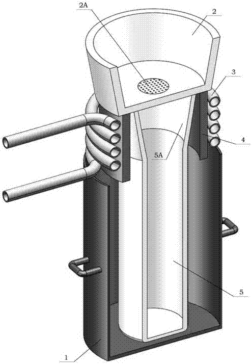
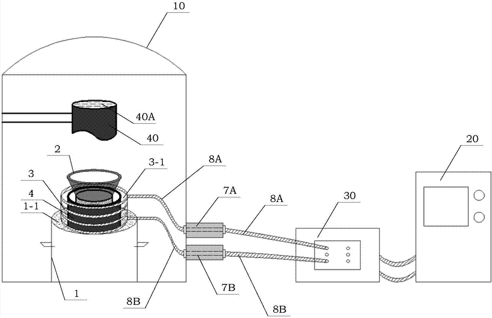
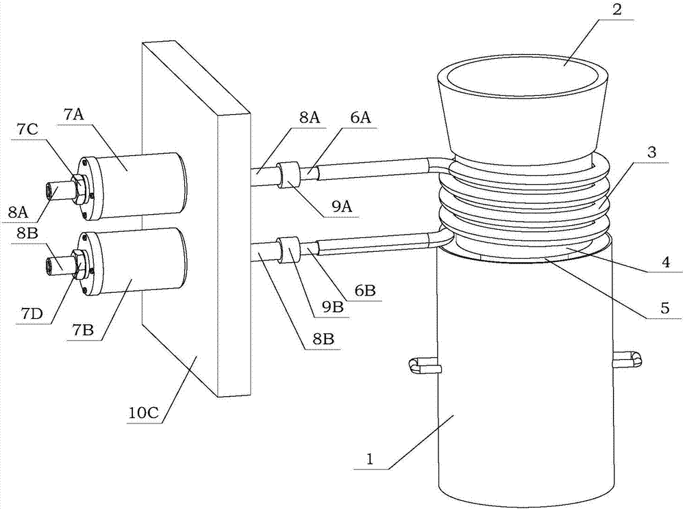
[0076] like figure 1The shown improved vacuum smelting equipment of the present invention adopts a vacuum induction furnace to smelt a nickel-based superalloy, and casts it in an yttrium oxide ingot mold. The specific method is as follows:

[0077] Step 1: Before closing the furnace cover and vacuuming, set the water-cooled copper plate as the cooling device and place it in the vacuum induction furnace. The upper surface area of ​​the water-cooled copper plate is 40% of the cross-sectional area of ​​the cast rod. Water inlet and outlet, and cooling water channels are set in the copper plate; the yttrium oxide ceramic ingot mold is preheated to 900°C and placed in the base. The segment inner diameter is 100mm. Place the base and the ingot mold on the water-cooled copper plate, and make the center of the water-cooled copper plate coincide with the center of the ingot mold, and place the induction heating coil outside the riser. The inner diameter of the induction heating coil i...

Embodiment 2

[0083] like figure 1 The improved vacuum smelting equipment of the present invention shown in the present invention adopts vacuum induction furnace to smelt nickel-based superalloy, and casts it in a magnesium oxide ingot mould. The specific method is as follows:

[0084] Step 1: Before closing the furnace cover and vacuuming, set the water-cooled copper plate as the cooling device and place it in the vacuum induction furnace. Water inlet and outlet, and cooling water channels are set in the copper plate; the magnesium oxide ceramic ingot mold is preheated to 420°C and placed in the base. The maximum inner diameter of the riser section of the ingot mold is 110mm, the minimum inner diameter is 90mm, The segment inner diameter is 90mm. Place the base and the ingot mold on the water-cooled copper plate, and make the center of the water-cooled copper plate coincide with the center of the ingot mold, and place the induction heating coil outside the riser. The inner diameter of the...


PUM


Abstract

The invention discloses a sequential solidification technology device and method used in vacuum smelting equipment. An induction heating coil is placed in a dead head section of an ingot die, and the feeding capacity of metal liquid in a dead head is enhanced through an induction heating method; a bottom cooling device with the cooling area smaller than the area of the cross section, at the bottom position of the ingot die, of a casting is arranged at the bottom of an ingot die base, the solid-liquid interface angle is reduced, and the metal liquid in the ingot die after pouring can be sequentially solidified from bottom to top. The solidification process control method is applicable to production of metal bar castings in the vacuum smelting equipment. Through the sequential solidification technology device and method, macroshrinkage and shrinkage porosity in alloy bar castings can be eliminated, the casting quality and the technology yield are improved, and the production efficiency is greatly improved.

Description

technical field [0001] The invention relates to the technical field of casting equipment and methods, more particularly, to a sequential solidification process device and method used in vacuum smelting equipment. Background technique [0002] In the production process of ultra-high temperature materials, in order to ensure that the produced materials have an excellent quality level, it is necessary to strictly control the chemical composition and improve the purity, which mainly depends on the melting technology. Vacuum melting technology is a key technology for ultra-high temperature material melting. [0003] During the casting process of the alloy liquid, when the solution is poured into the ingot mold, the liquid in contact with the wall of the ingot model solidifies first, and the liquid in the center part solidifies later. Due to the liquid shrinkage and solidification shrinkage of the alloy, voids often appear in the part of the casting that solidifies last. Large a...

Claims


Application Information

Patent Timeline
Patent Type & Authority Applications(China)
IPC IPC(8): B22D7/06B22D27/06
CPCB22D7/064B22D7/068B22D27/06
Inventor 张花蕊李一鸣张虎
Owner BEIHANG UNIV
Why Eureka
Try Eureka