Metal die tool

A metal mold and tooling technology, which is applied in the field of metal mold tooling, can solve problems such as uneven casting, waste of manpower and material resources, and loose casting, so as to reduce the use of manpower and material resources, facilitate disassembly and installation, and improve casting efficiency. Effect

Inactive Publication Date: 2017-02-22
TIANJIN LONGHE STEEL ALTERED METAL PROD CO LTD
0 Cites 5 Cited by

AI-Extracted Technical Summary

Problems solved by technology

During the use of metal molds, uneven casting and loose casting often occur, resulting in cracks and air bubbles inside the formed metal, which greatly reduces the casting quality of metal products, and metal molds need to be quickly processed during use. Disassemble and assemble the metal mold. At present, in order to achieve a higher q...

Abstract

The invention discloses a metal die tool comprising a base; a movement groove is formed in the middle of the upper end of the base; a lower die body is arranged in the middle of an inner cavity of the movement groove; a guide slide block is arranged at the lower end of the lower die body; a guide groove is formed in the bottom end of the inner cavity of the movement groove; the outer side of each of two ends of the lower die body is connected with the side wall of the inner cavity of the movement groove through telescopic guide rods; and the telescopic guide rods are sleeved by reset springs. Due to the matching action of first electromagnets and permanent magnets, a metal die can achieve the aims of sloshing and mixing in the use process, and the defects of raw material mixing nonuniformity and mixing deficiency in the casting process of metal products are avoided; and due to the actions of the second electromagnets, an upper die body is conveniently dismounted and mounted, the casting efficiency of the metal products is increased to a great extent, the defect of dismounting difficulty in the traditional fixing method is avoided, the consumption of manpower and material resources is reduced, and the practicability is very high.

Application Domain

Technology Topic

Image

  • Metal die tool
  • Metal die tool
  • Metal die tool

Examples

  • Experimental program(1)

Example Embodiment

[0015] The technical solutions in the embodiments of the present invention will be clearly and completely described below in conjunction with the accompanying drawings in the embodiments of the present invention. Obviously, the described embodiments are only a part of the embodiments of the present invention, rather than all the embodiments. Based on the embodiments of the present invention, all other embodiments obtained by those of ordinary skill in the art without creative work shall fall within the protection scope of the present invention.
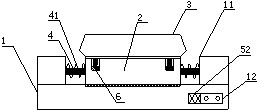
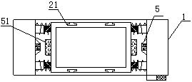
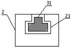
[0016] See Figure 1-5 , The present invention provides a technical solution: a metal mold tooling, including a base 1, a moving groove 11 is provided in the middle of the upper end of the base 1, and a lower mold body 2 is provided in the middle of the inner cavity of the moving groove 11, The lower end of the lower mold body 2 is provided with a guide slider 71, the bottom end of the inner cavity of the moving groove 11 is provided with a guide groove 7, and the guide slider 71 is embedded in the guide groove 7, and the guide slider 71 and The function of the guide groove 7 determines the movement path of the lower mold body 2 and avoids the phenomenon of running position. The outer sides of the two ends of the lower mold body 2 are connected to the inner cavity side wall of the moving groove 11 through the telescopic guide rod 4, And the telescopic guide rod 4 is sleeved with a return spring 41, the telescopic guide rods 4 are no less than four, and the telescopic guide rods 4 are arranged symmetrically along the center axis of the lower mold body 2, and the telescopic guide rod 4 The lower mold body 2 still has good toughness during the back and forth movement. The upper mold body 3 is parallel to the upper part of the lower mold body 2, and the upper end of the lower mold body 2 is symmetrically provided on both sides There are no less than four positioning grooves 21, the positioning grooves 21 are symmetrically arranged along the central axis of the lower mold body 2, and the lower end of the upper mold body 3 is symmetrically provided with positioning sliders on both sides 31, and the positioning slider 31 is inserted into the positioning slot 21. The role of the positioning slot 31 and the positioning slider 31 determines the fixed position between the upper mold body 3 and the lower mold body 2. The lower end of the positioning slider 31 A second permanent magnet is fixed, the middle of both ends of the lower mold body 2 is provided with a first permanent magnet 51, and the inner cavity side wall of the moving groove 11 is provided with a first electromagnet 5 corresponding to the first permanent magnet 51, Through the action of the first permanent magnet 51 and the first electromagnet 5, the purpose of making the lower mold body 2 move back and forth by changing the polarity of the first electromagnet 5, so that the casting between the upper mold body 3 and the lower mold body 2 The raw materials are fully uniform and mixed to avoid cracks and bubbles in the casting process of metal products, and improve the quality of metal casting. The bottom end of the inner cavity of the positioning groove 21 is provided with a second electromagnet 6, and the second electromagnet The outer periphery of the iron 6 is sleeved with an elastic rubber ring 8. The cooperation of the second electromagnet 6 and the second permanent magnet facilitates the removal and installation of the upper mold body 3 and the lower mold body 2. Before and after the use of the mold body 2, the second electromagnet 6 is cut off and energized to realize the fixation and disassembly of the upper mold body 3, which greatly improves the efficiency of metal casting and has strong practicability. The height of the second electromagnet 6 is less than the height of the elastic rubber ring 8. The side of the base 1 is provided with an inverter 52 and a controller 12 in sequence. The first electromagnet 5 is electrically connected to the inverter 52, In addition, the inverter 52 and the second electromagnet 6 are both electrically connected to the controller 12, and the casting materials inside the lower mold body 2 are mixed well through the action of the inverter 52.
[0017] Although the embodiments of the present invention have been shown and described, those of ordinary skill in the art can understand that various changes, modifications, and substitutions can be made to these embodiments without departing from the principle and spirit of the present invention. And variations, the scope of the present invention is defined by the appended claims and their equivalents.

PUM

no PUM

Description & Claims & Application Information

We can also present the details of the Description, Claims and Application information to help users get a comprehensive understanding of the technical details of the patent, such as background art, summary of invention, brief description of drawings, description of embodiments, and other original content. On the other hand, users can also determine the specific scope of protection of the technology through the list of claims; as well as understand the changes in the life cycle of the technology with the presentation of the patent timeline. Login to view more.

Similar technology patents

Classification and recommendation of technical efficacy words

  • Improve casting efficiency
  • Easy to install and remove

Piston ring casting technology

ActiveCN110814284AImprove casting efficiencyImprove the efficiency of sand mold makingCasting plantsFoundry mouldsMolding sandTempering
Owner:安庆海威尔机械有限公司

Efficient multi-layer overlapping pouring device for casting parts

InactiveCN109332601AImprove casting efficiencyReduced pouring timeFoundry mouldsFoundry coresMono layerCasting
Owner:HUBEI YAGANG METAL MFR

Building board pouring equipment

Owner:GUANGZHOU CITY CONSTR COLLEGE

Silver-ingot casting pipeline

InactiveCN104289701AImprove casting efficiencyMolten metal conveying equipmentsSolid structureIngot casting
Owner:耒阳市诚松有色金属再生有限公司
Why Eureka
Try Eureka