
Eureka
For R&D, Eureka makes reading and utilizing patents & technical documents easy.
Eureka AIR
Designed for self-driven R&D workflows. Generate viable solutions, solve complex R&D challenges, empower your innovation with AI.

Eureka Materials
Designed for material experts only. Revolutionize your material R&D, from search, analyze, to developing new materials.

TechResearch
Generate reliable direction feasibility study reports for your R&D in just a few steps.

TechSeek
Discover and master advanced knowledge NOW. Basics, ideas, possibilities, all at once.

TechMind
As an expert in R&D Theories, TechMind can generates customized viable solutions instantly.

TechRisk
Analyze your overall solution with one click, know your potential R&D risks in advance.

TechMonitor
Get weekly tech updates, stay abreast of the latest tech innovations and key insights.
Direct connection type machining central main shaft unit and rigid connection structure of direct connection type machining central main shaft unit and main shaft seat
A machining center and direct-coupled technology, applied in metal processing equipment, metal processing machinery parts, manufacturing tools, etc., can solve the problems of shortened life of spindle bearings, difficult control of transition fit, and heat damage of bearings, etc., to achieve convenient manufacturing and structural Simple, rigid effect
- Summary
- Abstract
- Description
- Claims
- Application Information
AI Technical Summary
Problems solved by technology
Method used
Image

Examples
Embodiment Construction
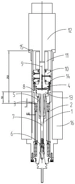
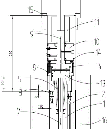
[0014] refer to figure 1 , 2 As shown, the present embodiment is mainly composed of a main shaft core 1, a main shaft sleeve 2, a main shaft bearing 3, a cutter cylinder 4, a pressure spring 5, a broach device 6, and a broach rod 7, and is characterized in that the main shaft core 1 Installed in the center of the main shaft sleeve 2 through the main shaft bearing 3; one end of the cylinder body 8 of the cutter oil cylinder is installed on the tail end of the main shaft core 1, and a coupling shaft 9 coaxial with the main shaft core 1 is installed on the other end; on the coupling shaft 9 A hollow rotary joint 10 is installed to provide the power of the cutter cylinder 4; the coupling shaft 9 passes through the hollow rotary joint 10, and then is connected to the main shaft motor 12 through a coupling 11; the piston 13 of the cutter cylinder is connected to the broach rod 7 , A pressure spring 5 passing through the broach bar 7 is installed between the piston 13 of the knife c...
PUM
 Abstract
Description
Claims
Application Information
 - R&D Engineer
- R&D Manager
- IP Professional
- Industry Leading Data Capabilities
- Powerful AI technology
- Patent DNA Extraction
Browse by: Latest US Patents, China's latest patents, Technical Efficacy Thesaurus, Application Domain, Technology Topic, Popular Technical Reports.
© 2024 PatSnap. All rights reserved.Legal|Privacy policy|Modern Slavery Act Transparency Statement|Sitemap|About US| Contact US: help@patsnap.com